How -to Automotive Lighting, Pt.2
We’ll Check the Headlight Switch and Its Power Supply. Then We’ll Start On Headlight Aiming.
EDITOR’S NOTE: LAST month we started our series on automotive lighting with a look at headlights, which we’ll continue here. There were 11 photos in the first installment, so we’ll resume with Photo 12.
Headlight Switches
The headlight switch itself can fail, leaving you without lighting. In all my experience, failure translates to “No Headlights.” It is certainly possible, however, that there could be an intermittent problem. There may be some signs before failure such as roughness of operation or excessive looseness in the knob.
Sometimes, a headlight switch can be cleaned and effectively rebuilt, and that may be the only option. On a more common one such as a ’60s Chevrolet, I would just replace it. This will likely be more of a challenge than a dimmer switch as you usually are dealing with a dash-mounted headlight switch that will require odd body positioning to reach, and often a special tool may be required. Check your shop manual for your application to determine if it is within your skill level (and mostly this translates to your level of patience).
Should you decide to tackle it, be safe and disconnect the battery’s ground terminal before proceeding with any work under the car’s dash.
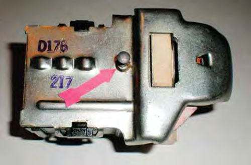
Shown in Photo 12 is a typical GM light switch. While this one is from my 1987 El Camino, there hasn’t been much change over the decades. The red arrow in photo 13 points to the spring-loaded button on the bottom that must be pushed to allow the removal of the knob and stem. Simply press in on this button and pull the knob straight out.
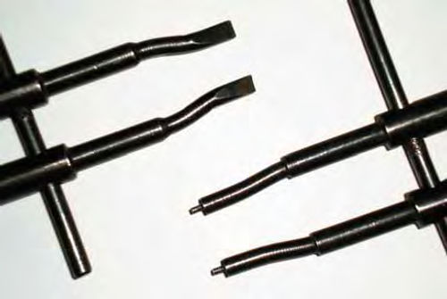
Reaching that button, however, can sometimes be a challenge. The front of the switch is threaded, and a collar, located behind the knob, is used to secure it to the dash. For many vehicles a special tool is needed to remove this collar. The tools you see in Photo #14 were for vintage camera repair, but they are also useful in removing some of the different retaining collars. Handy tools can also be made out of inexpensive putty knives and by reforming the tips on needle nose pliers.
If your headlights aren’t working, disconnect the wiring harness from the headlight switch to verify it is receiving current. There should be current present at all times. This is normally a tight-fitting plug. It’s often easier to remove the switch from the dash, get it to an open area and then disconnect it. If, however, you are able to disconnect it without removing the switch, that’s great.
Once it’s disconnected, use your test light to see if there is current. On the GM headlight switch in Photo 12 there is a “cutout” in the ceramic heat sink over to the right where two spade connectors are located, one behind the other. The one closest to the ceramic supplies the dome lights, the one behind it is the battery connection. (Note: The arrow in Photo 12 points to the battery terminal.)
If you disconnected the battery, remember to reconnect it for testing purposes. If you have battery current to the headlight switch, but when activating it found no current at the dimmer, you have either a defective/worn-out headlight switch, or an open in the wiring in between. If you have a new or “known good” headlight switch, plug it in. This is the quickest way to find out if the switch is the problem. If not, reconnect the originals witch and turn the headlights on and off while using your test light to probe for current. If none is found exiting the switch during this test, you have confirmed the switch is bad. The majority of the time this will be the case.If, however, activity is found, you will need to examine the wiring between the dimmer and headlight switches.
No Power To the Light Switch
If there is no power in the wiring to the switch, you will need to backtrack the wiring to determine why. There may be a broken wire, or even the possibility of a blown “fusible link.” Your Service manual will let you know if they are used on the vehicle, and direct you to their locations. Many vehicles use these links on heavier current applications. They are actually a part of the wire and appear as “a plastic-coated wide spot.” Think of them as a sealed inline fuse. Usually labeled “fusible link” they can create an open in the wiring but they can be cut out and replaced.
If you need to make repairs to these links (and actually to any electrical wiring) always solder your connections and seal with heat shrink tubing where possible. Where heat tubing cannot be used, sealing a repair with a couple of coats of liquid electrical tape is the next best thing. If you choose to use electrical tape, I would recommend the rubber type that fuses to itself without adhesive. Thistape seals out air and moisture very well, but can’t tolerate too much engine heat or UV rays.
Aiming the Headlights
There are several ways to go about aiming the headlights. You can create a wall chart and project your lights onto it, or use mechanical equipment that grabs onto the lamp via suction cups.
Let’s begin with the wall projection chart. This may sound like you’re just using your garage door to check your lights, but it is much more than that. This method is also handy when checking headlights (or any add-on lights) that don’t have the three guide points on the lens. (These guide points are required for use with suction-type equipment.) The chart we will create is specific to the vehicle we are working with. Once a target has been established for each headlight, it will act as a gauge to judge their horizontal and vertical adjustments.
The basics are to establish a horizontal line(s) that is centered with your headlights and then to find the vertical centerline(s) of each lamp.
The generally accepted method is to start with a relatively level floor, make certain your tires are properly inflated, and the vehicle is sitting at its normal ride height. The goal is to have the headlights parallel with and 25 feet away from the surface you’re projecting onto.It’s Sometimes easiest to measure 25 feet and snap a chalk line, or put down a strip of masking tape that’s slightly wider than the vehicle (if the tape will stay secured to the floor). It is important that this line is parallel with the surface your chart will be placed on Now, use this line as a guide and position the headlights over it.
I would recommend placing several pieces of white poster board slightly wider than your vehicle up on your projection surface. Secure it with tape, staples, or whatever works best for you.
Now, follow these three steps:
1. Measure from the floor to the center of your headlights and transfer this measurement to your chart creating a horizontal line the width of the poster board. For example, the horizontal line for my Caprice is 26” above the floor. Should you have a four-headlight system where they are situated one above the other (vertically mounted like a ’65-’67 Plymouth Fury) you will establish two parallel horizontal lines.
2. Next, find the center of the vehicle and make a centerline on our chart. (This step will require an assistant’s help.) Measure the windshield and find its center. Use a short piece of masking tape to make a vertical line to indicate the location. Repeat the same procedure with the rear glass. Finally, while standing behind the car, sight through the rear glass, aligning the two pieces of masking tape. This is the center. With your guidance, have your assistant make a mark that corresponds with it on the wall chart. You can use a carpenter’s square to create the vertical centerline. Use the horizontal line(s) you have already established and square off from that.
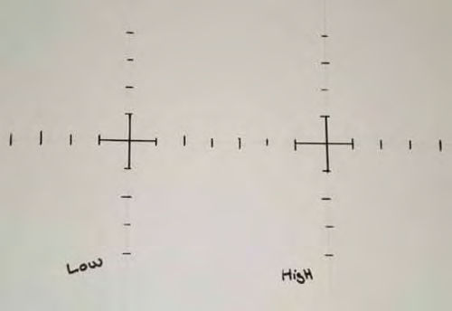
3. Measure the distance between lamps on-center. For example, the low beams on my Caprice are 60” apart, and the high beams are 46”. Splitting these numbers, my low beam target will be 30” to each side of center, while the high beam will be 23”. Mark these spots and using a square, create four vertical lines. Also identify each target you have made as “High” or “Low” to indicate which beam they represent.
Photo #15 is a close-up showing the left portion of the targets created for both low and high beams. The targets we have established are considered zero vertical and zero horizontal. This is measured in inches at 25 feet (this is the standard). You can also measure off inches in all four directions from each established target on the wall chart (as you can see inPhoto #15).This is particularly important should you live in a state with safety inspections that require adjustments other than zero/zero. Read up on the local requirements and allowable tolerances. Creating this scale will allow you to compensate and make your own “state specific” target as well as work within tolerances they have set.
With all of the measurements known, I found it easiest to create the wall chart on my living room floor, then line it up to the proper height, and center it with the car’s centerline.
The Caprice’s headlight aiming chart ended up with one horizontal and four vertical lines to create the targets. If, for example, your vehicle is a ’65- ’67 Plymouth Fury (with vertically mounted headlights as mentioned earlier), you will only have two vertical lines. Regardless of what you are driving, or how the headlights are configured, you will end up with a target for each lamp.
This process is time consuming and you will want to do your initial setup before it is dark if you’re working outside. Once dark, turn on your low beams and notice the high intensity spots on the wall chart.
Compare them to their targets. Older vehicles usually require headlight bezel removal to access these adjustment screws, while later ones, probably most made from the ’70s on, don’t.
If you need to raise the bright spot to get on target, tighten the vertical adjusting screw slightly while watching the beam. If you feel uncertain about the location of the high intensity spot of the lamp you are working with, make a measured adjustment in either direction, such as two full turns clockwise. Watch the projection while doing this. It’s easy to return to where you started when using this method, and it will usually verify the “bright spot” location. (Having a helper make this initial test adjustment while you watch the chart is a big help.) The horizontal adjuster screws are located on the side of the bulb. This Left/right adjustment is performed like the vertical. You may choose to complete all the adjustments to one bulb at a time, or possibly do both vertical adjustments, followed by both horizontals. It makes no difference, just be sure the previous adjustment didn’t move. If you are working with a two-headlight system you are essentially done, as the high beam element is pre-aimed when manufactured and is not adjustable. You can check your lights while switching between the high and low beam modesto verify they are changing. If a beam appears to be considerably off target, replace the bulb. This is unlikely, but not impossible. With a four-light system you would now click on your high beams and proceed as you did before only using the targets you marked “High.” If It makes it easier, you can use a piece of cardboard or a similar item to block off the low beam light while making this adjustment. As with most anything, it’s always a good idea to double-check your adjustments. If you have no local requirements, a maximum of plus or minus four inches is the generally accepted tolerance.
Mechanical Headlight Aimers
There are several other types of equipment for aiming lights, but the one practical for us is the suction-cup type.
These mechanical units use levels and rangefinders (like those used in older cameras) to calculate the proper adjustment. These can be found at auto swap meets and on-line from sites such as eBay. They are affordable to the hobbyist, or the minimal cost could be divided between club members. The prices will vary depending on condition and completeness of accessories. Stick with the Hoppy B4 model; it’s been around for years. I would avoid some of the earlier suction-type products due to limitations in application, as well as availability of parts, if needed.
There are advantages to this type of equipment over a wall chart. The first that comes to mind is you can do the job any time of day, inside or out, because the headlights remain off during the entire operation.
There is no guesswork, which means better accuracy and consistency in light aiming. And if your floor isn't level, the unit can compensate for it.
The only requirement here is that each lamp has three undamaged guide points.
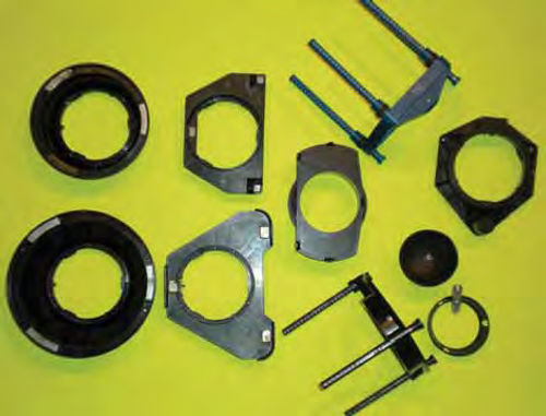
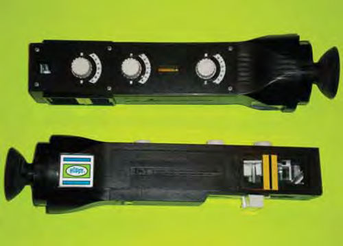
Photo 16 shows a pair of headlight aimers manufactured by Hoppy, and Photo 17 has one of each of the various accessories: fixed adapters for large and small round; large and small rectangular; what is referred to as mini quad headlights; a large and small universal adapter; suction cup swivel adapters; and calibration fixtures. These universal adapters are primarily for the more contemporary aerodynamic composite headlight housings with the guide points, but can also be used in place of the other adapters. The large universal adapter (black, lower right) can also be used in place of the large round and large rectangular while the small universal adapter (blue, upper right) can take the place of the small rectangular, but not the small round. This is good to know if you make a purchase and some adapters are not included.
While you might prefer to have the dedicated adapters, at least you know what these universal ones can be substituted for. Universal adapters can be used with the suction cup “swivel” extensions to accommodate the slope of some headlight fixtures and the adjustable rods have corresponding numbers that match numbers on the lens of the headlight fixture.
Next: We’ll continue working with the headlight aiming tools.