
Taking a Look at Our Tires & Brakes, Pt. 2
Now That We’ve Removed the Wheels and Inspected Them, Let’s Turn Our Attention to the Front Disc Brakes, Rear Drums, Hoses and Bushings.
Editor’s note: Since your wheels and tires keep you in contact with the roadways, inspection and maintenance procedures are necessary on an ongoing basis. Last month we took a close look at some wheels and tires, and considered several rotation techniques. Now it’s time to work with our brake drums, shoes and pads. We’ve had 16 images so far and will start here with Photo 17.
Removing the Rear Drums for a Brake Inspection
Before racing to get the tires back on the vehicle, take the opportunity to inspect a few things while the wheels are off. Brakes are a primary thing to check, and it’s usually easy to do that if you have disc brakes or brake drums that just slide off. On the rear of my Caprice the drums simply slide off, providing a look at the brake shoes, springs and wheel cylinder. If you used a brake pedal lock or have the park brake applied, either would need to be released. The drum is designed to pull straight off, but if it won’t, there could be several different things holding it in place:
1. Although it’s highly unlikely that you’ll encounter them on an older vehicle, GM has employed one-time-use metal clips to hold the drums on. Presumably this was to keep the drums in place when going down the assembly line, and the first time the drums are removed these clips are pried off and thrown away. Usually there was one per wheel, and it was just pushed on over one of the axle studs. So if you spot them on your drums, the drums have most likely never been off the vehicle. To remove them, place a large screwdriver against the perimeter edge of the retaining clip, and gently strike it with a hammer. This will distort it, and it can then be pulled off with pliers or side cutters.
2. The drum could be rusted to the axle. Look where the center hole of the drum fits over the axle boss. Back in Photo 8 (last month) the axle boss is shiny and bright, showing no signs of rust, but that’s not always the case. With older vehicles where the drums haven’t been off in some time and especially on those that have been subject to northern winters, they may actually be rusted to the axle. If you see no looseness or movement around the axle boss, as though the drum were one with the axle, try spraying the area with penetrating oil. Use a small wire brush to help work it in, and then apply some more. After giving it some time to do its job, take a hammer and strike the drum on the edge. Once is usually enough to free it. You also can strike the axle boss, but in doing so don’t get carried away, and be careful not to create an edge. If you have a “soft face” hammer, for example one made of lead or copper, hold it against the axle boss and strike it with another hammer. Should the drum still remain stuck to the axle, you will likely need to enlist the aid of an oxyacetylene torch to heat the drum’s mounting flange around the axle boss. This will break the rust bond between the two.
Once the drum shows independent movement from the axle, you can attempt to slide it off.
3. If the drum pulls off a little, but then stops, this is likely due to brake drum wear. It’s possible there is a ridge on its outer edge that may catch on the shoes themselves. A trick that will often work if the condition is minor is to try and remove the drum while rotating it. First place the vehicle in neutral and then start rotating the brake drum by hand, while attempting to remove it at the same time. It works like you are threading the drum off the shoes. If that doesn’t do it, push the drum back on completely and then try rotating it in the opposite direction while pulling. Be careful of the backing plate behind the drum to avoid getting your hand or fingers pinched while rotating. If this method doesn’t work, it may be an indication that brake service is necessary. Loosening the brake shoe adjustment will be required to bring the shoes far enough away from the drum to clear the wear ridge. In most cases a brake adjusting tool is inserted through a slot in either the backing plate or brake drum and the star wheel adjuster is backed off. Usually there will be a rubber or plastic dust plug in the access slot, and should it be missing, purchase replacements at the parts store and pop them in when the procedure is finished.
If the vehicle has self adjusters, (most Chevrolets started using them in the early 1960s) you will additionally need to use a small pocket screwdriver or pick tool alongside the adjusting tool. It will be used to hold the self adjuster off the star wheel, allowing you to rotate it. Once loosened sufficiently, the drum should then slide off. Remember, if you had to loosen the adjustment to remove the drum, it will need to be readjusted once the inspection is completed and the drum reinstalled.
Close Encounter With a Brake shoe and Adjuster
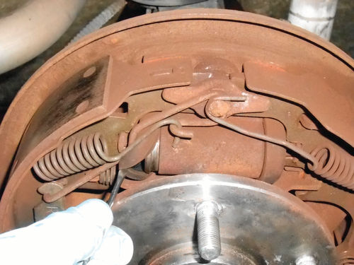
Photo 17 has several things worth noting. That’s the brake shoe front and center in the photo. Note that the lining is riveted to the steel shoe. Look at all the rivets and inspect the lining-to-rivet clearance; look for loose rivets and cracks in the lining material. If there are any doubts or questions, replace the shoes and perform any other needed brake service. Should anything appear questionable or out of place, compare the right wheel to the left wheel. This will confirm spring orientation and appearance.
To the right of the shoe is a shiny metal arm with a spring in between it and the brake shoe. This is the self-adjuster that was previously discussed. Older designs will look different, but they function in the same manner. Notice that the bottom of the self-adjuster has a bend in it. This is the business end where it makes contact with the star wheel adjuster. This vehicle has the access slot for brake shoe adjustment in the brake drum. Looking again at Photo 8 in last month’s article, you can see the steel “knock-out” still in place at 12 o’clock on the drum. A hammer and drift pin would be needed to punch the knock-out inward. It would be retrieved once the drum was removed. With access through this slot in the brake drum, a small pick tool with a 90° bend on the end would be inserted alongside the adjustment tool and used to lift and hold the adjuster off the star wheel. Had the access slot been in back, through the brake shoe backing plate, a small pocket screwdriver would be inserted alongside the adjuster tool to push and hold the adjuster away from the star wheel.
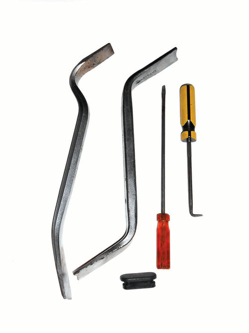
Photo 18 shows a couple of different brake adjusting tools along with a typical rubber dust plug and tools useful in holding the self-adjuster away from the star wheel. Before moving on, take note of the axle seal to make sure it isn’t starting to sling grease.
Checking Wheel Cylinders and Brake Drums
Photo 19 shows pulling the dust boot away from the wheel cylinder and checking for leaks. You can use your fingertip or pocket screwdriver to lift the boot away from the wheel cylinder, and if fluid is present (usually it will come dripping out), the wheel cylinders will need to be replaced or rebuilt. Always replace or rebuild in pairs. Some boots tuck into the wheel cylinder so they are not as easily pulled away for inspection. In that event, use something like the long pocket screwdriver shown in Photo 18 and insert it into the boot alongside the wheel cylinder’s push rod. Gently move it around touching the bottom of the cylinder and then remove it to see if it’s wet. Essentially the screwdriver has become a dipstick. You can also insert the screwdriver so that it catches the lower edge of the boot where it presses into the cylinder and pop the lower edge free. It shouldn’t take much effort to do so, just make sure you catch the perimeter edge. If you see the screwdriver flexing the soft area of the boot outward, stop, or you might puncture through the boot. When done properly you will only see the lower edge of the boot coming free of the cylinder. Again, if fluid runs out, it needs to be replaced. The boot can be pushed back in position with your fingertip.
If you are concerned because you’re unfamiliar with the design of the wheel cylinder, don’t be. The rubber boot that is visible on the outside is to keep brake dust from getting past it and into the wheel cylinder. The push rods at either end of the cylinder extend through the dust boot, and are in contact with the cylinder’s pistons. Some applications have eliminated the push rods, and the cylinder’s pistons are redesigned to directly contact the brake shoes. The actual seals (or cups) are on the inside of the piston, and there is no danger of accidentally damaging them during this checking procedure.
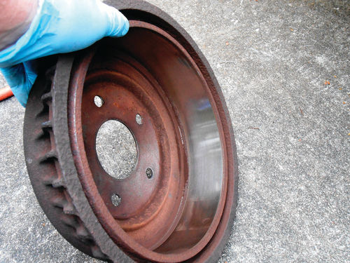
Don’t forget to take a look at the brake drum. Preferably you want a smooth, constant friction surface, with little or no ridge on the edge. Photo 20 shows a recently turned drum with a clean, smooth surface. If there is some minor scoring to the drum surface, but all else seems OK, this is normally nothing to be concerned about until the brake linings are due to be replaced. If there is a substantial rust ridge on the edge of the drum, use a file or coarse sandpaper to reduce it. This will make installation easier. Now replace both the brake drums, and readjust the brake shoes if they were loosened for the drum’s removal.
You also can check to see if both the rear brakes are applying. This is a simple test, and isn’t high tech. With all the brake drums installed on the vehicle, use the brake pedal lock or have an assistant depress the pedal while you try to rotate each of the drums. They should both lock securely. If you find one does but the other slips, there possibly is a problem with the wheel cylinder or maybe a steel brake line is kinked, eliminating proper flow. If both brake drums fail to hold (or for that matter don’t release when pedal pressure is removed) the flexible brake hose to the rear axle may be internally collapsed, or if the vehicle has a tandem master cylinder, that too could be the cause. Brake hoses can look fine on the outside, but that doesn’t always mean they are good. The rear brake hose on my 1966 Malibu became restricted and was causing the brakes to drag. They eventually would release, but it would take several seconds after I removed my foot from the brake pedal. Replacing the hose eliminated the problem.
Front Disc Pad Inspection
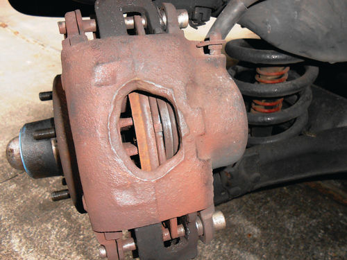
Front disc brakes are easily inspected once the wheels are off. On this vehicle, as can be seen in Photo 21, you can view through the hole in the caliper casting and see quite a bit. Starting from the left you are looking at:
1. The cooling vents in the center of the brake rotor.
2. The inboard friction surface of the rotor.
3. The inboard disc brake pad.
4. The disc pad backing plate.
6. And finally, the piston’s rubber dust boot.
In most instances, when the brake pad is the same thickness as its backing plate, it’s time for new brakes. You also can view the rotor and caliper from the opposite side and judge the thickness of the outboard disc pad as well. The Caprice still has some usable life remaining with these linings.
While you are there, take a look at the flexible rubber brake hose that extends from the caliper to the frame. The one in Photo 22 has a light coating of dirt on it, and that’s to be expected. Inspect for cracks or rubber peeling away from the hose, abrasions or any signs of fluid leakage. There also is the flexible hose connected to the rear axle that was previously mentioned, but to thoroughly inspect it you will have to crawl under the vehicle. I am trying to limit this article to working at the four corners of the vehicle, and inspect as much as possible without going under it.
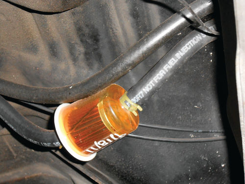
A good flashlight will work to spot leaks, but probably not cracks, unless they are severe. Photo 23 shows what an average digital camera can capture when zoomed in. I know, this isn’t the rear brake hose, but instead the fuel hoses at the tank, just above it. It captured the upside-down date on the fuel filter, and the printing on the hose. Had there been any serious rotting and cracking of the rubber hoses, the camera would have caught it. This photo was taken with the camera held in the left rear wheel well.
A camera can be a useful tool in many situations, and recording images allows you to study them again at a later time as well. With this vehicle supported properly on jack stands, there is certainly no reason you couldn’t crawl under it if you were in the mood. Without a doubt, that will yield the most thorough inspection. As was done with the rear wheels, both front wheels also can be checked to make certain they are locking securely when the brake pedal is pressed.
Always reference your vehicle’s shop manual for further information on brake service and inspection. Should you feel uncomfortable performing any of these tasks, and suspect there may be issues needing attention or further inspection, complete the tire inspection and rotation, and then have a qualified person check the brakes for you.
Inspecting Rubber Bushings

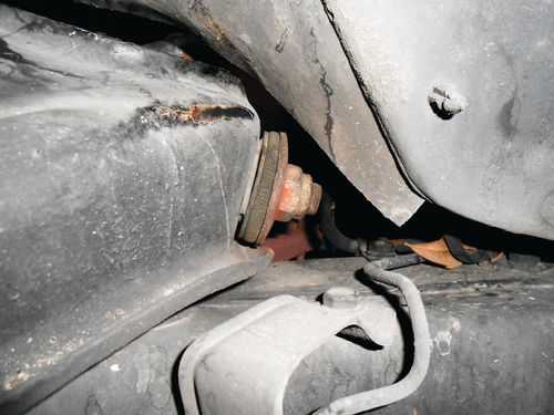
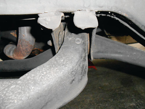
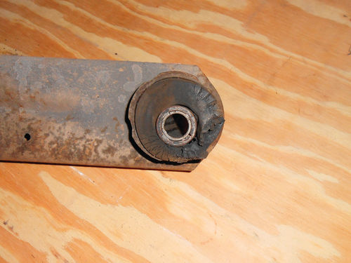
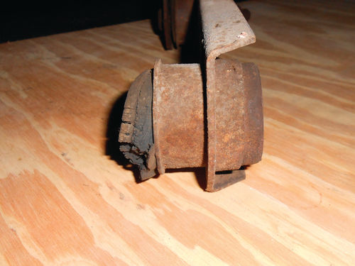
There are a number of bushings that aren’t too difficult to see while the wheels are off, so let’s take a look. At the rear of the vehicle, Photo 24 shows the lower control arm bushing where it bolts to the axle housing. Look on either side in between the arm and mounting bracket for rubber peeling or bad cracks, and rust coming from the central area of the bushing. Look at it from the side and judge if the mounting bolt is centered and concentric with the bushing. Photo 25 is the forward mount of the same arm where it connects to the vehicle’s frame. The camera was held below and slightly to the rear of the bushing for this image. The camera’s flash really lit up the dark corners, making inspection via the image very easy. Photo 26 shows the upper control arm where it connects at the top of the differential. From this view it’s easy to tell that the bolt is concentric with the outer diameter of the bushing. If it were not, the bushing would require replacement. It may look simple enough to do, but don’t be fooled. This one was replaced about a decade ago, and if there hadn’t been a screw-type hand press in the tool box, I wouldn’t have been able to do the job. Photo 27 is a good example of a bushing that’s no longer concentric. The rubber has simply deteriorated with age and allowed the formerly centered mounting to move. Photo 28 shows what you don’t want to see when looking at a bushing from an end view.
Before heading forward, take a look at the lower shock absorber bushings as seen in Photo 29. There is some paint overspray on the rubber bushing, but that’s OK. This bushing doesn’t have a steel center core like the ones previously mentioned, and the rubber is softer, intended to help absorb some of the impacts. These happen to be air shocks, and this vehicle is sometimes used for towing. These small bushings often help to support quite a bit of weight. For that reason it’s not unusual to see these bushings a bit out of shape, but of course if they are badly worn, it’s time to explore your options.
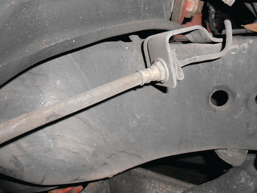
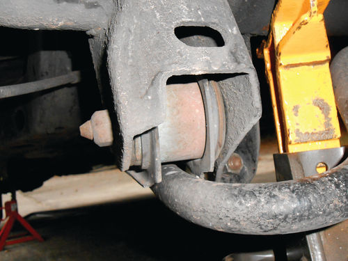
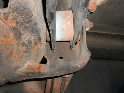
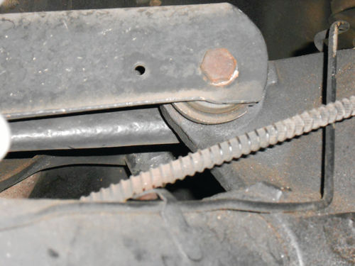
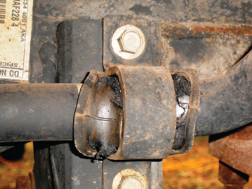
Moving to the front of the vehicle, notice the upper control arm bushing seen in Photo 30. Both the upper and lower control arm bushings on the Caprice were replaced 13 years ago and reflect 150,000 miles of travel since then. The upper bushings aren’t perfect, and are starting to show some small cracks, but they are still solid and will maintain vehicle alignment. Photo 31 shows one of the lower control arm bushings. These lower bushings will typically outlast the smaller upper bushings by many years. The front stabilizer bar secures to both frame rails via a metal U-bracket and rubber bushing as seen in Photo 32. These are still in great shape, but a look at Photo 33 shows what you don’t want to see. This photo was taken of a similar bushing on the rear of my friend Roger’s 2003 Ford F53 motorhome chassis. The bushing has become very distorted and worn through, and the bracket is making metal-to-metal contact with the stabilizer bar. It appears as if the bushing were trying to escape. This type of bushing usually is easy to replace.

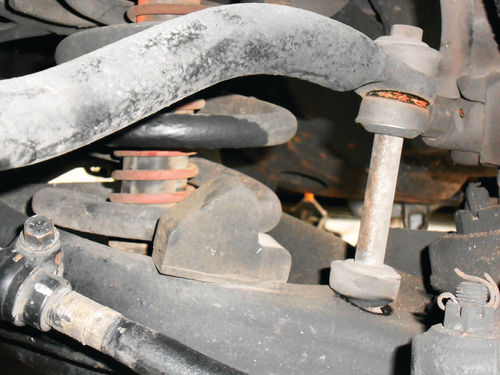
Back to the Caprice again, where Photo 34 shows how the stabilizer bar is connected to each lower control arm with what’s called stabilizer links. This is a fancy name for an assembly of four rubber bushings, washers, a long bolt and a nut. As they age, vertical cracks will develop in the rubber bushings, or they may wear and become loose. The small gaps visible in Photo 34 are due to the vehicle’s weight being supported by jack stands under the frame rails; allowing the lower arm to stretch downward.
Consider an Extended Search
That covers most of it, but if you wish to keep looking around while the vehicle is up in the air, don’t let me stop you. This inspection could include the exhaust system and/or looking for fluid leaks from the engine, transmission, differential or even the hydraulic shock absorbers. Look at parts of the vehicle that are symmetrical such as suspension and some steering components, and pay attention for noticeable “differences” from one side to the other. Should you spot something and are unsure about it, reference your shop manual.
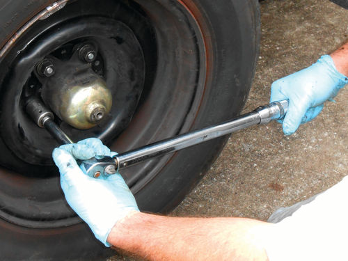
Now it’s time to replace the wheels in their new locations. Tighten the lug nuts hand tight, and then put the brake pedal lock (or your assistant) back into position to secure the brake pedal. I choose to tighten the wheels to 85 ft.-lbs. of torque as is being done in Photo 35. Tighten the lug nuts evenly and in stages, skipping over every other one, tightening the wheel in a star pattern. My method is to first tighten all the lug nuts on all the wheels to 45 ft.-lbs., then 65 ft.-lbs., and finally 85 ft.-lbs. Use a smooth continuous action if you desire the torque value to be accurate. Rapidly snapping the torque wrench or a momentary pause when tightening the lugs will yield inaccurate torque. Once the task is completed, don’t forget to reset your torque wrench to its lowest setting before putting it away. On this old Craftsman wrench that’s 10 ft.-lbs.
All that remains is to replace the wheel covers, make sure the vehicle is in park, use the parking brake, and then safely lower the vehicle back to the ground.
As you read this series, it might appear that this would be an all-day affair, but that’s not the case. Unless you get sidetracked performing some needed repairs, this is more like a leisurely couple-hour job.


