
Suddenly, the Headlights Went Out,Pt. 3
We Need to Make a Bracket for Our New Headlight Switch. Then We’ll Install the Switch… and Something’s Still Wrong.
IT ALL STARTED when we were driving along with the high beams on and the headlights stopped working. We replaced the dimmer switch, to no avail, and then pulled the headlight switch only to see that the mounting tab on the switch’s plastic bracket is broken. That’s where we stand now and we’ll be starting with Photo 27.
Making a New Bracket Is an Option
Crafting a new bracket won’t be too difficult as long as your original one isn’t too badly broken. If it is, tape and glue it together so that it can be used as a guide to form a paper template. It doesn’t need to be strong enough to use, just as long as it holds together well enough that it can be used for a pattern. Things like partially missing/broken mounting tabs are fairly easy to estimate as far as their size, and can be trimmed down if made too large.
You will need to have some basic metal-working tools like a hand jigsaw, metal shears or other means for cutting the piece out of metal stock. An electric grinder (either bench type or hand held) and files to smooth the rough edges is essential. Finally, you’ll need a vise or metal brake and hand seamers for bending and forming the metal piece.
Start by using a piece of thin poster board to make a template. This part isn’t flat, so the bends will need to be negotiated. Cutting, taping and possibly even temporarily gluing the template together with rubber cement will yield an adequate model to work with. Look again at Photo 25 in last month’s issue. There is a small protruding boss below the left mounting tab. It has no function for the El Camino’s application, so to make life easier in forming the template it was trimmed off. Had it been an essential piece, I would have started by creating a small hole in the poster board to fit over it, and then formed the bend below it, and so on. A template would be created, and once the metal bracket was formed, a boss would be made out of steel and secured in the correct location.
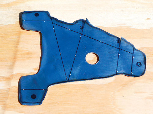
What you’re looking at in Photo 27 is poster board that has been formed around the original bracket. A bolt has been positioned through the center hole to secure it while duplicating the shape of the bracket. The thinner the poster board, the easier it will be to work with. A pencil was used to trace around the perimeter and then some, but not all of the excess was trimmed off. Though it is very tempting to trim it all at once, it’s a much better idea to do this trimming in stages, leaving a bit extra. As you remove some of this unneeded bulk; it will become easier to form, and the fit will likely change slightly. Once you are sure all is finished, any remaining excess can then be trimmed. This part is certainly three-dimensional, so enough extra poster board was intentionally left to form the right side in Photo 27. Several cuts and bends were made, and then some tape was used to hold the form. Should you accidentally trim too much, another strip can be added by simply taping it in place.
Photo 28 shows the rear view of the newly formed template next to the bracket. The holes are marked for each arm, but haven’t been punched out yet. The center hole will need to be enlarged to 1 ⁄2". The smaller hole was the best choice during the template-making stage. The recess you see around the 1 ⁄2" hole on the original bracket appears to have been done to add strength to the plastic, so there is no need to worry about duplicating it. But there I go assuming again. To be safe the original plastic bracket was temporarily secured in the dash once again, and the bezel placed back into position. The clearance between the bracket and bezel was checked. You can actually look through the headlight switch knob hole in the bezel and see that there is about 1 ⁄8" clearance between it and the bracket, so, as suspected, the absence of the recess won’t be an issue.
Before the template is untapped and flattened back out, all the bend lines will be marked with a sharpie so that information can be transferred to the piece of metal. This part will have a number of bends; two are simply minor tweaks in the top mounting tabs. Cut or remove any tape and flatten out the template. Position the template on a piece of 20-gauge (.036") cold rolled steel or something similar that’s easy to bend and work with.
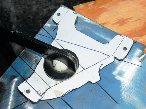
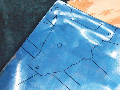

Photo 29 shows the template has been clamped to the metal so that it won’t move around and all the bend lines extended out beyond the template onto the metal. Remove the template and what you have is seen in Photo 30. The next step is to extend those bend lines back across the piece as they were on the paper template.
A good place to begin is by creating the 1 ⁄2" center hole. It’s easier to perform this task prior to cutting out the form. A larger section of metal is easier to hold; this piece was about two feet in length. Of course there is a practical limit to this way of thinking. If it’s a very large sheet it will need to be reduced to a manageable size. Photo 31 shows a Blair hole cutter being used for the task. It leaves a cleaner cut; especially in thin sheet metal where a drill bit will pull at it. I drilled a small pilot hole first as this keeps the cutter from wandering. Photo 32 shows the actual cutter set. The tool you see here includes seven cutters from 1 ⁄4" to 5 ⁄8" and is decades old. For product information visit their website at blairequipment.com.

If you will be using a drill bit to create the hole, and are working with a small section of metal, make certain to secure the work piece. Avoid the possibility of getting injured by a piece of rotating sheet metal. The drill bit can easily grab hold of the metal and give it a spin.
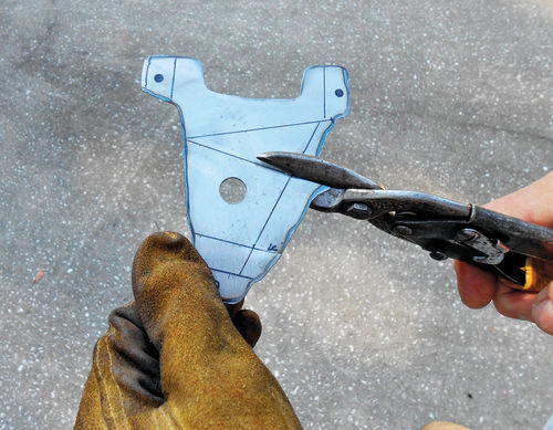
After the drilling you may need to tap the metal flat with a hammer and use a file to dress it off. The alignment notch for the switch will be formed later. It’s time to cut the piece out of the sheet of metal. Look at your available options and choose the best you have to do this task. An electric hand jigsaw with a fine metal blade will work well, but I have a recently purchased plasma cutter that needs to earn its keep, so it will be used here.
To be on the safe side, the piece was cut a little larger than its outline. The thin metal can easily be worked down with a file or grinder if needed, but making it bigger is another story. Photo 33 shows the roughly cutout piece. Short cuts are being made on the right. This will allow the metal to be bent, ultimately forming the side. The holes have been marked in each tab, and a hand punch will be used with a 7 ⁄32" punch once the part has been temporarily fitted in the dash and these locations verified. It’s tempting to punch them out now, but the odds are they probably wouldn’t line up exactly.
There are bend lines all over the place on the top surface of the piece, but none on the rear. When the piece is being formed, it will likely be bent in both directions, so for this reason it’s a good idea to have those same lines on both sides. If you look closely at Photo 34, you might notice tiny star-like punch marks along the lines. This has nothing to do with the constellation of Orion. These punch marks leave small dimples on the back of the piece which helps to confirm where the lines should be when marking the opposite side.
While it’s not too much of an issue on a small piece of metal, it’s a big help (at least for me) on larger or more complicated pieces.
Start Bending
Start from the center and work outward. My first bend is the line directly above the 1 ⁄2" hole for the switch. I formed it in a standard 5" bench vise, positioning the line at the top edge of the vise jaw with the front of the piece facing me, and then bending the metal backward 90°. Next was the angled line directly above it, bending it in the opposite direction, once again forming a 90° bend. This bend was a bit more difficult than the first, but with the aid of a hammer tapping along the bend line of the metal it then became fairly easy to obtain the desired position.
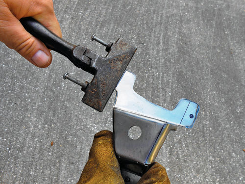
Now the top of the new bracket is starting to resemble the original part. The short lines directly below the 1 ⁄2" center hole are next. This will form the lower mounting tab. The first line below the hole was bent 45°, followed by the final line just above where the small lower tab hole is marked. This was bent 45° in the opposite direction. Other than the right side of the bracket, it’s looking more and more like the original plastic bracket. A pair of hand seamers was used to make the slight offset bends in the top two tabs as shown in Photo 35. There wasn’t much metal to grab onto when forming the right side. The seamers were just too wide to use as they were designed, so the narrow side of the tool’s jaw was used to grab and bend each section of metal back as much as possible. The bends were closed together more tightly by using the corner of the vise jaw for support, and tapping them down with a hammer. The piece was then positioned in the dash to see how it lined up. The top tabs were a bit fat, having too much metal and needed some trimming, but otherwise they looked to be on target. Even the location marks for their holes looked good. A little re-bending was required to move the lower tab closer to its desired location. Once the mounting tabs looked good, and the center hole was positioned properly with relation to the dash bezel, the bracket was removed. The top holes were punched exactly where they had been marked via the template. The lower mounting hole however was relocated and then punched out. If needed, these mounting holes can be slotted to allow for positioning. This is easily accomplished when using a hand punch for the holes. Slightly overlap the previously made hole in the desired direction and punch an additional one.
When test fitting the new part be patient, it’s a trial-and-error process. Don’t expect it to line up without adjustments the first time. Odds are the final product won’t look exactly like the original, and it doesn’t need to, just as long as it positions the light switch knob in the correct location, at the proper depth, and doesn’t interfere with anything. This isn’t something like your hood ornament that you will see every day, it’s a structural piece concealed within your dash. Obviously you want it to look as good as possible, and as long as you are willing to admit to making it, then all is OK. After all, this isn’t for NASA, it’s for my Chevrolet.
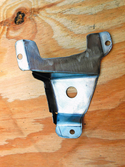
In Photo 36 the part is shown after its test fitting with the holes punched and the three small sections of metal bent back to now form the right side. These three sections will be welded together, but a good two-part epoxy like JB Weld will also work. Another option is to use a small screw or rivet if there is enough overlap in the sections of metal, as long as it won’t interfere with the switch mounting.
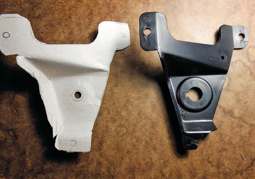
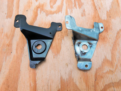
The original plastic bracket is about .090" thick, and the only place this will be an issue is with the 1 ⁄2" center hole, where the threaded collar goes through the bracket to secure the switch. The collar will bottom out first against the alignment tang of the switch before it ever gets snug on the new thinner metal bracket. To take care of this minor problem, a washer will be tack welded in position on the back side of the new bracket, but once again, a good two-part epoxy is a perfect option. Photo 37 gives you a side-by-side comparison at this stage of the project. Notice the washer is now in place, and the sections forming the side have been welded as well. Remember to make certain that there are no sharp or rough edges on the new bracket that could cut you or chafe wiring. All that remains is to form the locating notch for the switch using a small file, and a quick coat of paint to discourage rust. The depth of the notch is simply judged by eye. As long as it’s deep enough, you are fine, if you go a bit overboard, it isn’t an issue here.
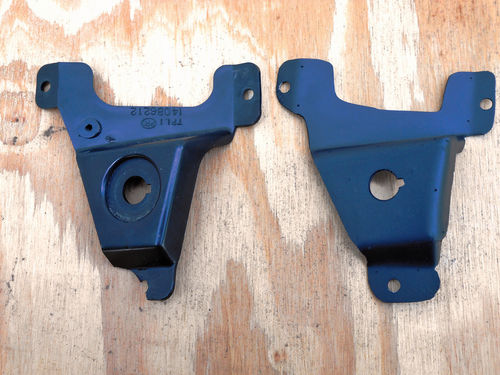
Finally, Photo 38 shows the original plastic part to the left, and our finished product to the right. Now you have a bracket that will last.
Usually there is no shortage of parts for a Chevrolet, especially of this vintage, but with some vehicles you may find yourself in a situation where a part just isn’t available. Having some basic tools, poster board and 20-gauge cold rolled steel (or even 18-gauge) on hand isn’t a bad idea. I have several 2' x 5' sections of CRS standing up against the wall behind my tool box. It’s handy stock for fabricating items like this, or making small repair panels.

Replacing the Headlight Switch
Headlight switch replacement essentially is just the reverse procedure of removing it…nothing difficult or complicated.
Due to the fact that the new metal bracket is thinner, shorter screws were used to hold it in place; otherwise they might bottom out creating a loose fit.
First align the new switch in the bracket and snug the retaining collar. Now install the knob and shaft by simply pushing it in until it stops. Pull it out again at least once to make sure all feels right, and that there are no surprises. Firmly press the wire connector into the switch, and then give the lights a quick test to see that all works. If you disconnected the negative cable, it will, of course, need to be reconnected temporarily.
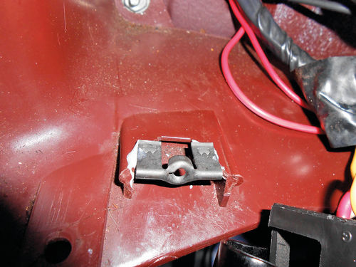
Next connect the three mounting tabs of the bracket to the dash mounts. The lower dash mount was found to be damaged. Yes, more broken plastic. There is a metal clip that the screw threads into. It has ears on each side, and once pushed onto the plastic dash mount, “brads” on the inside of the ears bite into the plastic and hold on. That is as long as there is still plastic to grab. JB Weld epoxy was used to secure the metal clip to the remaining plastic as can be seen in Photo 39. We’ll allow 24 hours to pass before any further operation of the switch, making certain the repair is fully cured. Had the dash mount been in worse condition, a more extensive rebuild would be required, possibly involving plastic welding. In Photo 40 you can see the finished product in use, securing the new light switch within the dash. All that remains is to reposition the dash bezel and replace its seven screws.
OK, We’re Done With This… Um, No We Aren’t
If you think that’s the end of the story, sorry, not so fast. The next day the headlight switch was put through the motions. All seemed fine as was expected, at least initially. The high beams were once again left on as a confidence builder. I left for a moment to grab something to drink, and upon my return saw the headlights of the El Camino flashing at me as though there was a police speed trap just ahead. Had I not known better, I would have been staring to see who the person was in the vehicle flashing the lights at me. What in the world was going on? This problem had been answered once the headlight connections were all cleaned! I wasted no time in removing the bezel and light switch. Thankfully it only takes a few minutes to do so. The new switch was removed, and the old one put back in its place. Remember the switch was replaced due to the instrument lighting issue, not the high beam failure. With the old switch back in place, the instrument lighting was again flickering, but the high beams burned without failure. The new switch was then checked with an ohm meter as described in the manual. “The condition of a circuit breaker may be verified by removing it from the circuit and checking the resistance. A good circuit breaker will have less than 1 ohm resistance between the two terminals.” These terminals have the large red incoming power wire, and the yellow wire that goes to the dimmer switch connected to them. Photo 41 shows the proper hook-up, and the reading of .1 ohm is well below the maximum. The new switch tested fine. Possibly the circuit breaker was good, but for some reason was opening at a lower amp value. Regardless, this switch was going back, so a return trip was made to the parts store. Lifetime guarantee or not, I had lost any confidence in this maker’s product. Simply replacing the switch with another one from the same manufacturer was unacceptable.
This time, however, an AC Delco headlight switch was again showing up on the computer as available, so it was ordered. I know what you’re thinking, because I was thinking it too. When this switch arrives it will most likely be the one that was initially returned because of the broken Bakelite.
One more visit to the parts store. Well, the box it arrived in appeared to have taken a tour of the world. There were labels pasted all over it of previous destinations, and, finally, one with my name on it. Wow, what a sinking feeling. I was starting to think about just living with the flickering instrument lights, it really wasn’t such a big deal anyway.
When the box was opened there were no loose broken pieces inside, so a close examination of the switch was made. After all, someone may have just disposed of the incriminating evidence.
As worn as the box was, the switch at least looked OK.
Upon my return home, the switch was plugged back into the vehicle, without any further reassembly. All looked and felt good. The high beams were left on for one solid hour without failure.
AC Delco is simply my preference. Many years ago they offered a number of free classes at the GM training centers located throughout the country. This was aimed at independent garages, mechanics and others who were interested in learning. I took advantage of all the courses, so I feel some alliance to their products. This doesn’t mean there are no other good manufacturers out there, but at least in my recent encounters they have certainly out-performed the others.

So the new bracket was again secured to the dash, and the panels put back together a final time.


