
Suddenly, the Headlights Went Out, Pt. 1
We Were Riding With the High Beams On and They Quit. It Must Be the Dimmer Switch. We’ll Replace It.
IT WAS JUST after 5 a.m. on a Sunday morning and we were on our way to our season opening monthly swap meet. The El Camino was loaded and pulling our 10-foot enclosed trailer with items we hoped to sell, which would yield the space for the items I hoped to purchase.
There was little to no traffic on the road as you might expect that early in the morning and only a few street lights in this rural area so my high beams were blazing brightly ahead. I was sipping on some coffee while driving and talking with my wife about what kind of day we might have at the swap meet…when suddenly the headlights went out. There was some ambient light, but not much.
My first reaction was to flip the dimmer switch. We were in luck; the low beams came on and remained lit. There were probably six or seven miles remaining before we would reach our destination, and once at the swap meet, I wouldn’t need to be concerned because the drive home would be during daylight. To play it safe, I skipped taking our normal shortcut and instead drove through the center of a small community where there were street lights. Thankfully there were no additional lighting failures or resulting encounters with the local police. Upon leaving the market that afternoon, the lights were momentarily tested and were again working properly.
Experience Points to the Dimmer Switch
If a failure is repeatable, it’s simply a matter of following the flow of current through wires, switches and connectors to determine where the loss of power occurs. A basic test light will get this task done. If, on the other hand, the problem can’t be made to reoccur, about the best you can do is to visually inspect the wiring and connections and then make a decision based on process of elimination. Even the bulbs may need to be considered. If the lights went out and remained off it is possible the bulbs failed, but having four individual bulbs fail simultaneously is unimaginable. If, however, the vehicle in question has an unknown history, is new to you; or none of the bulbs have ever been seen working, never overlook the obvious.
I suspected this was a dimmer switch issue, and the switch probably needed to get hot before it would fail. The switch is constantly getting used (at least in my vehicles), so this would be a likely candidate. After all, twice our 1986 Chevrolet Caprice had experienced very similar lighting failures, and the culprit was the dimmer switch on both occasions. Actually, the original dimmer switch on the Caprice was replaced after more than two decades of trouble-free service with one made by an unknown manufacturer. That one lasted about a year and a half. When going to replace it the second time I noticed Advance Auto Parts had access to one manufactured by AC Delco for a few dollars more, and purchased it. That was five years ago, so it clearly was a good decision.
Once again Advance Auto Parts was visited to see if a dimmer switch was available from AC Delco for the El Camino, and indeed there was one for $24. The switch wasn’t marked with country of origin, and I am always curious, as well as hopeful that it’s a domestic product. The original corrugated shipping box is unmistakably domestic. It’s also marked “Flint, MI”, and the labeling on the box states “AC Delco, Detroit MI.” An educated guess says most likely it was made here in the states.
Replacing the Dimmer Switch
The El Camino’s dimmer switch is located on the steering column, about halfway down, just behind the large bracket that secures the column and is actuated by a long metal rod between it and the signal lever. There is nothing that needs to be dealt with behind the steering wheel for this issue; it’s all down below the dash area. Replacing it isn’t as straightforward as the old floor-mounted switches; it will certainly take you longer, but it’s not too difficult.
It’s a good idea to disconnect the negative battery cable to be on the safe side. This will also help avoid discharging the battery. There are two floor lights and an overhead interior light that will no doubt put a drain on the battery.
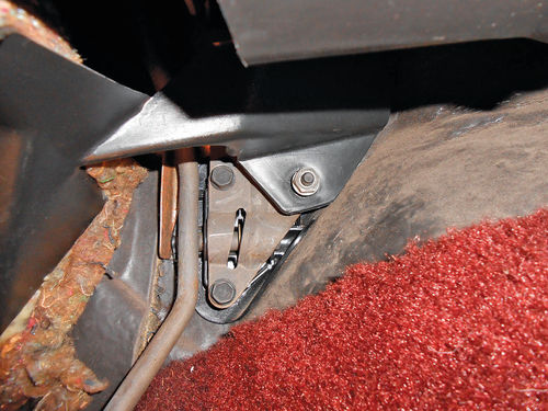
To obtain access, removing the air conditioning duct panel below the steering wheel gets things started. This is accomplished by removing the four visible Phillips screws as shown in Photo 1, then slide off the vent hose and set it aside. There is a lower panel above the pedal area that conceals the fuse box and hides wiring that would likely otherwise be visible. An 11mm nut secures the inner rear corner, just above the accelerator pedal linkage seen in Photo 2. The front is held up by two screws that require a 7mm socket to remove. If you have a nut driver, or handle to fit ¼" drive sockets, that’s a good choice for this. As you can see in Photo 3, the panel can now be dropped down and removed. That opens things up considerably. Note that these two panels could have just as easily been removed in inverse order if desired.
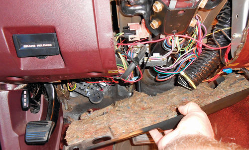

To get to this point has only taken a few minutes, but the pace will slow down as we move forward. Photo 4 gives us the first look at the dimmer switch. It is located on the left side of the column, just behind the large column support bracket. This bracket will need to be loosened and removed before being able to reach the switch.
From previous experience when replacing the switch on the Caprice, I found there was more weight in the upper steering column than had been expected, and preferred not to just let it hang without any support.
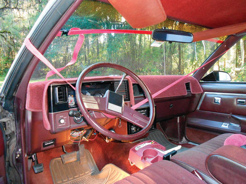
Now don’t laugh too loud when you look at Photo 5, but a simple 12'-long strap was used to limit the column’s downward travel. As you can see, it goes under the column behind the steering wheel, and then around the windshield. This isn’t a suggestion from Chevrolet regarding this type of project, but instead just something that made me feel better.
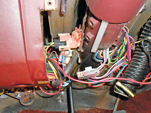
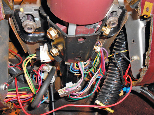
Next remove the bracket’s four bolts that thread into the column with a 13mm socket. Before removing the two nuts, I chose to mark the location on the bracket using a sharpie. There is no reason that anything should change, but if things don’t line up the same when it’s time to replace this bracket, the marks will certainly tell me. A 15mm socket makes quick work of removing these two nuts, and the bracket is removed. A look at Photo 6 finally reveals the switch. Notice the actuation rod that extends up to the directional lever. This simply slides into the switch. There are two screws securing the switch, and they are located at about 10 o’clock in relation to the steering column. You can’t help but wonder why they couldn’t have located these screws on the lower side of the switch. It would appear there’s adequate room to do so.
The wiring connector must be removed to give access to the rear screw. There are two plastic tabs, one located on the top, and the other on the bottom of the connector that latch into the ears on the switch. Squeezing the tabs on the connector inward and pulling out will remove the connector. A small pocket screwdriver or something similar can be helpful here in depressing the tabs. It will require a little wiggling while going back and forth depressing the two tabs. Below the switch is a vacuum hose for the cruise control that was in the way, so it was easily twisted and disconnected. Photo 7 shows that we’ve finally reached our destination. The two screws that secure the switch have 8mm hex heads. Before you begin to loosen the screws you can try to make a reference mark on the column indicating the position of the switch, although it’s a bit difficult in this location. I decided to just make any final adjustments before the switch was tightened. Besides, the new and old switch didn’t appear to be identical, anyway.
The forward screw was loosened without too much difficulty, but the same can’t be said about the rear one. In Photo 7 you can see that there is a piece of steel framework positioned closely, just above the switch. Look closely at the photo and you might even notice the semicircle cut out in the steel to add clearance for the plug that connects to the switch. This gives you an idea of how confined it is.
To gain more space, the strap supporting the steering column was loosened. As it turned out, the weight of the column isn’t that much of an issue here, so it could have been removed. (The column of the Caprice definitely wanted to sag considerably more.) Even so, the space was too tight for my hands, so as you see in Photo 8, a couple of small wood blocks were used to push the column inward, away from the metal framework. A typical ¼" drive ratchet and socket wouldn’t fit within the confines. A ¼" drive flex head ratchet might have done the trick had I been able to find mine. Ultimately both a Craftsman 8mm ratcheting box wrench, and a Craftsman 8mm wrench from their “Midget Combination Wrench Set” were used. (Years ago they were referred to as an ignition wrench set.) These are thin, stamped metal wrenches, nothing too special. Anyway, the rear screw broke free, but it never loosened. A wrench had to be used to remove it the entire way. I tried putting just a socket on it and rotating it with finger tips, but nothing doing. Adding a knurled spinner to the socket seemed like a good idea; this would greatly increase my ability to rotate the socket, but it was then too long to fit into the space. Eventually the screw was removed, a quarter turn at a time, and out came the switch.
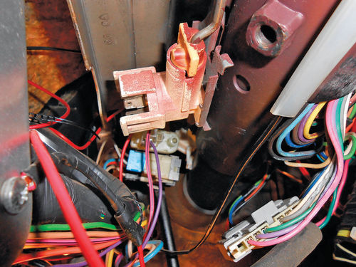
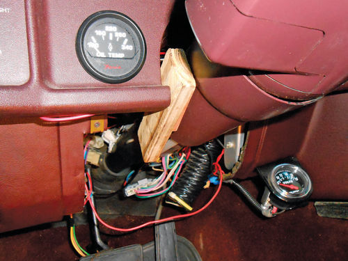
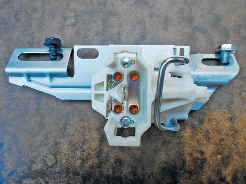

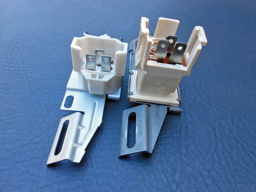
Photo 9 shows the new switch, as it would secure to the column. In the photo the right side would be toward the steering wheel, and, obviously, the left toward the floor. Note the u-shaped piece of metal to the right that resembles a large staple. It keeps the switch closed and can be removed and discarded.
Some Basic Electrical Checks
Before continuing, you can perform some basic electrical checks on the old switch, or even with the new switch in place, if desired. You will need a test light, and if the switch is to be tested while still mounted to the column, a jumper wire will be necessary in order to reach, and back probe the wiring connector. With the wiring connected to the dimmer switch, temporarily reconnect the negative battery cable, and run the tests listed below by depressing the actuator to change modes.
With the headlight switch in the “headlights on” position, there should be current entering the dimmer switch through the yellow wire. This yellow wire goes to the single spade terminal centered to the right (Photo 9).
Low beam mode — current passes through the switch to the lower left terminal, and is delivered to the tan wire only.
High beam mode — current passes through the switch to the upper left terminal, and is delivered to the green wire only.
Different vehicles may have used different colors for the wires, but if it is a GM product of this era, the terminal locations on the switch will be the same. Keep in mind when testing the switch that if it’s an intermittent problem, or possibly requires the switch to heat up before it fails, it may very likely test OK. In that case, leave the headlights on to see if the failure will reoccur. With the El Camino, I had confidently made the decision to simply replace the dimmer switch with a new one.
Now looking back at Photo 9, notice that the screws are different in color. More than that, the threads are not identical, as can be seen in the Photo 10 close-up. My first thought was that this was what caused the rear (dark) screw to be so stubborn when coming out. It must be the wrong screw. Looking closely at the steering column, and more specifically the location where these two screws thread in, the forward screw threads into the cast metal of the steering column, while the rear screw threads into a section of sheet metal above. This explains why they are different screws. Keep this in mind and don’t get them confused.
Photo 11 shows the new switch to the left and the one just removed to the right. The new switch is almost an inch lower in profile. This should make life a bit easier during installation. Before continuing, disconnect the negative battery cable if it had been reconnected for testing. To make things possibly go a bit smoother installing the switch, a small amount of grease was placed on the threads of each screw. Then each was threaded completely into their locations while the switch was still out, and then removed. It may help, and certainly can’t hurt anything.
Time to Install the New Dimmer Switch
Positioning the new switch and lining up the actuating rod is easy; installing the screws is the hard part. The bigger you are, the more difficult it will be to get comfortably positioned to do this task. I found that sitting on the concrete driveway with my back somewhat against the inside door panel, and my left shoulder pointing inward toward the door hinges worked as well as anything. This allowed me to rotate my upper body and get my hands into the best position to hold the switch and replace the screws. Sitting on a foam cushion helped too.
Starting the uppermost screw (closest to the steering wheel) wasn’t too difficult. After probing around until the hole was located, the screw was started by hand, and a ¼" drive 8mm socket was used in between two fingers to snug the screw, and then back it off slightly. This is tight enough to hold the switch in position and lined up with the rod, but also allows for it to be slid back and forth for final positioning. For the lower screw a mirror was used to help locate its hole. As can be seen in Photo 9, the lower mounting slot of the switch is rather long, easily twice that of the upper mounting slot. That, and the fact this screw location is the more difficult to reach and get started are all good reasons to narrow the target area by finding the hole with a small mirror. You are basically poking around blindly, hoping that you don’t drop and lose the screw before you find the hole. Once found, I managed to use both index fingers to get it started. The grease that was used earlier on the screw threads indeed helped with this more stubborn screw’s installation. The 8mm socket was used to thread it in via fingertips; much easier than its removal. With both screws now threaded in but loose, the switch was positioned where I felt it should be.
If you look at the old switch in Photo 11, you’ll see the bright metal mark in the long lower mounting slot. This is where the screw was located. It’s just about in the middle of the slot, so by feeling with my fingers the switch was slid until the new one was in approximately the same position, and the screws were secured with a wrench.
The wood blocks were removed, and before going any further the directional lever was pulled back while listening for that distinctive click. It sounded good, and had about the same feel to it. Had it not, the screws would have been loosened and the switch repositioned.
Next is to plug in the wiring connector and reconnect the vacuum hose that was removed for better access. The battery ground cable was momentarily reconnected to verify that all was indeed working, and it was. The steering column bracket was then repositioned, and the bolts and nuts were all loosely started as seen in Photo 12. (If you look back at the earlier photos, especially 4 and 6, you can see how much more room there is between the wiring connector and the metal framework due to the shorter switch design.) First the bolts are tightened that thread into the column, followed by the 15mm nuts that secure it. You can see the black sharpie marks above each nut, these were the reference marks made earlier before removal. As previously stated, there is no reason they shouldn’t line up, but if for some reason they don’t, you will know there is a problem.
Once all has been tightened, it’s time to replace the vent duct panel. Slide on the hose, line it up and install the four screws. Finally, replace the lower panel. Position the right rear corner on the stud over the accelerator pedal linkage and then loosely start the nut. Next go and start the other two screws, and when all is lined up, snug everything. All is back together, and everything seems to be working fine.
Driving Along Again With The High Beams On…
It’s two weeks later, and this is the first outing since the new switch was installed. Once again it’s an early Sunday morning drive and we’re heading to a newly formed swap meet about 60 miles north of us. About 10 minutes into the drive the high beams quit working, just as they had done before.
The dimmer was clicked, and the low beams came on, and stayed on. Immediately I realized the assumption that the dimmer switch was at fault was wrong. Of course this wasn’t a diagnosis, just a decision (OK, a guess) based on previous history with a very similar vehicle of nearly the same age. This wasn’t the first time something like this has happened, nor will it probably be the last. It’s very tempting to skip the troubleshooting and diagnosis because you feel so certain about a problem. When you’re correct, you look like an automotive genius to your family and friends, but when this happens you realize you tie your shoes just like everyone else.
I am not going to beat myself up over this, even though my momentary genius status had been removed. After all, we’ve had the El Camino for over 16 years, and the switch had never been replaced so it’s not unrealistic to think it would most likely fail somewhere in the not too distant future. Thankfully, this was a relatively inexpensive part.
So Here’s Where Things Stand
The high beams failed on two separate occasions after being on for close to 10 minutes and replacing the dimmer switch had no effect. Later on, (during daylight) the high beams were briefly tested, and came on as normal, but to this point they hadn’t been left on for any length of time to see if they would fail again. How long would it take, and what else might happen?
Next we’ll check the shop manual to see where we might go from here.


