Suddenly, the Headlights Went Out,Pt. 2
Replacing the Car’s Dimmer Switch Didn’t Solve Our Problem. So We’ll Check the Shop Manual to Determine Our Next Move.
LAST MONTH WE were driving with the high beams on and the headlights quit working. We replaced the dimmer switch and the lights went out again. Obviously, we need a new approach to this problem. (Regarding images, we’ll be starting this month with Photo 14.)
What’s the Next Step?
The factory shop manual is a great tool, so why not see what Chevrolet has to say with regard to troubleshooting the lighting problem. If you have a factory manual, take some time and familiarize yourself with it by reading the general introduction, symbols, troubleshooting and repair procedures. This will make using the manual(s) easier. In addition, here are a few common electrical terms that you might encounter, and their definitions:
“Open,” or Open Circuit = a break or opening in an electrical circuit which prevents the flow of current. A blown fuse, broken wire or an uncoupled connector are all examples.
Ground = the return path of current to the battery. This is commonly through the frame, engine or connected sheet metal components. When referring to an electrical defect, it’s generally considered an “unwanted copper to iron connection,” such as worn wiring insulation allowing a wire to make contact with a grounded surface.
Short Circuit = to provide a shorter electrical path instead of following the prescribed path. This is usually referred to as an “unwanted copper to copper connection,” such as within a winding, or two wires contacting each other in a harness.
When it comes to shop manuals, I must admit that the 1987 version is much less enjoyable to read than some of my older 1960s factory manuals. This is certainly due to the inclusion of so much more information (emissions, electronics, etc.). The read now seems more difficult with the wording short and abrupt. Factual, yes; but a smooth easy read? No.
My manual is actually a combination of a larger service manual (ST-329-87), with an electrical diagnosis supplement (ST-329-87EDM), which includes another 22-page supplement (ST-329-87S). There is some general information in the large manual with regard to electrical issues, and this note which is worth mentioning:
“Disconnected and rerouted wires must be corrected or taken into account before any diagnosis can be performed.” The older a vehicle is, the more likely it’s had some wiring modifications. If “non-factory” wiring is encountered while investigating a circuit, a general rule is — if the work looks very neat and professional, the added wiring probably isn’t an issue. On the other hand, wiring that looks haphazard may likely be a problem.
Now after saying that, I am referring to the splicing of wires into a circuit, not the load at the end of these new circuits. Any additional “loads” added to the circuit in question would all need to be investigated. These issues don’t usually occur due to a simple wire repair, but more often when someone has added something, or thinks they have a better idea. The only wiring modifications under the dash of this El Camino were made by me, when several gauges were added. The lights for these gauges were wired to the fuse panel instrument circuit; the headlight circuit remained untouched.
The electrical diagnostic supplement essentially covers the “basic electrical checks” that were mentioned last month after the dimmer switch was removed. Additionally it mentions this with regard to high beam failure: “If the high beams do not light, but the high beam indicator lights, check the LT green wire for an open.”
This wire draws its current after the dimmer switch from the high beam (green wire), and goes to the indicator light in the dash. This light-colored green wire can be seen in the wiring schematic shown in the manual.
As well it mentions this with regard to the headlight switch:
“Voltage is applied to the light switch at all times. The light switch includes a self-resetting circuit breaker. The circuit breaker opens when the headlight circuit draws too much current. When the circuit breaker opens, it interrupts the current flow. With no current flow, the circuit breaker cools off and resets automatically.” It goes on to state that if your headlights won’t turn off, replace the headlight switch.
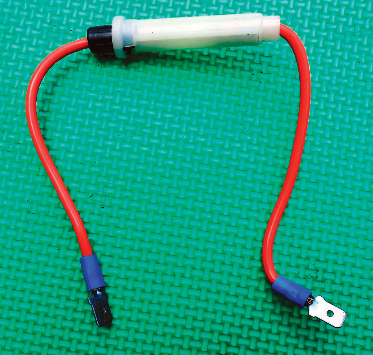
The manual suggests making a fused protected jumper wire with a 15 amp fuse for performing some checks. Photo 14 shows a fuse holder with a heavy duty 12-gauge wire exiting each end. I purchased several of these some time ago at a swap meet, but you can find them at your local auto parts stores too. This one uses the old-style glass fuse, but the fuse style is irrelevant. Just make certain it’s rated to hold a 15A load. If you’re unsure, purchase one that has heavy gauge wire. Male spade connectors were crimped on the ends so it could plug directly into the dimmer wiring harness, safely bypassing the switch.
It’s Time to Perform More Electrical Checks
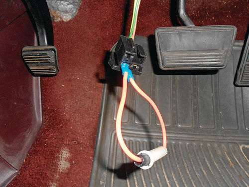
Once again the vent duct panel and lower panel were removed. The view resembles that seen last month in Photo 4, with the only difference being that the new dimmer switch has been installed. The wiring connector is disconnected from the switch, and pulled down below the dash where it is easier to handle. The issue is the high beam circuit, so the fused jumper wire is plugged in between the cavities connecting to the yellow wire and the green wire as seen in Photo 15. This bypasses the dimmer switch. The headlights are turned on; all four headlights and the high beam indicator all light, just as they should.
Next is simply giving it time. Had the headlight failure been immediate, or was constant, you would quickly know if the dimmer is the problem. In situations where it takes some time to act up, you will have to wait it out to see if the problem has been corrected or still exists. The previous track record would indicate there should be a failure in 10 minutes or so, and there was. The headlights went off, but then came back on again.


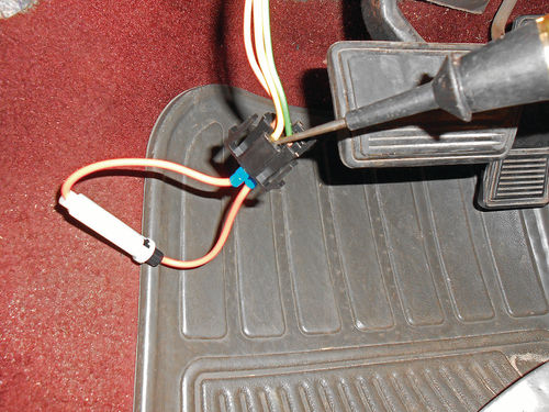
While not disturbing anything, a test light was used to back probe the connector at the yellow wire as shown in Photo 16. This is the incoming power wire from the headlight switch. The test light would light, and then go off, and it would keep repeating this sequence. This was happening due to the automatic resetting circuit breaker within the headlight switch referenced in the manual. So, presumably, for some reason the load of the high beams was too great.
The wiring was followed from the firewall bulkhead connector toward the headlights, and the wire loom opened to visually inspect the green wire. All looked OK. The fact that the wiring is protected in this plastic loom, and the fender well is also plastic pretty much assures the wire isn’t grounding out in that location. It is possible the wire could be shorting against another wire within the loom, but there was no evidence of that. The green wire continues to travel within this plastic loom across the radiator support to the headlights on the right side of the vehicle. There is no easy access to this portion of the wire, and part of it travels between the air conditioning condenser and a transmission cooler. It didn’t appear to be disturbed or damaged so the decision was made to inspect the headlight sockets, and clean the connections at the headlights.
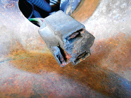
Photo 17 shows the socket for the left low beam. You can see the plastic had melted at the high beam connection. The green wire and connector were removed from the plastic socket, cleaned and reinstalled. While the plastic socket certainly shows its age, the wires and connectors all looked pretty good once cleaned. With all the headlight connections clean and tight, the lights were again turned on to see what would happen. This time they remained on without any failure for well over 30 minutes. The jumper wire was removed, and the connector plugged back into the dimmer switch. Again the lights were tested, and even with switching occasionally from low to high as normal driving would dictate, all still seemed fine.
Unfortunately I didn’t think of it until after all the connections were cleaned, but why not take a reading with an amp gauge to see just how much load the circuit is carrying. An induction amp gauge was clamped over the green wire (Photo 18) and it indicated 12.5A in the high beam circuit. I hadn’t located any specs for this, although 12.5A seemed like a realistic value, so for a comparison the same reading was taken on our 1986 Caprice. A reading of 12A was obtained. This vehicle uses the same four headlights, with essentially identical wiring, so that sounds good. So apparently all that remains with this project is to replace the two dash panels; and then be prepared for well-lit early morning drives in the future.

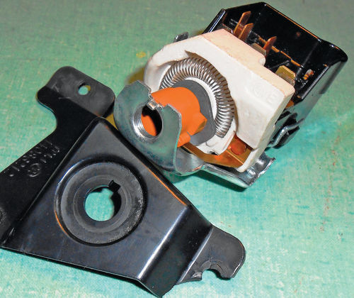
The only problem is that sometimes on these early-morning or evening drives the dash instruments aren’t so well lit. Now this isn’t an issue of dusty, dirty or burned out bulbs in the dash. All will work fine for a while, but if you rotate the headlight knob to turn on the interior lights, or vary their intensity, the dash lights may not come back on. Essentially moving or disturbing the knob for whatever reasons will likely end up with flickering or no instrument lights. Wiggling/twisting the knob back and forth will quickly restore the dash lights. There is a rheostat incorporated in the headlight switch to control the intensity of the instrument lights. After all some people don’t want the instruments too bright, while others do. If you look at this old switch in Photo 19, it’s that semi-circular looking “spring” that’s set into porcelain in the front of the switch. The switch you see in the photo was removed about eight years ago from the El Camino for the same issue. Obviously it takes awhile before I will dispose of some things. This problem with the instrument lights comes with age and for vehicles where a switch is still available the simple solution is to replace it with a new headlight switch.
With some vehicles reaching and removing the switch can be a bit of a challenge, but this vehicle is easy.
Another trip was made to the parts store. While they had a headlight switch for my application for $18…on the shelf with a lifetime guarantee, they also had access to one made by AC Delco for $33.
As tempting as the lifetime guarantee was, I again chose AC Delco. It arrived the next day and when the parts clerk opened the box, there were several chunks of loose Bakelite that had broken off the side of the switch. The switch may have been OK, but why take a chance. When he checked about reordering, it was shown as not being available. He wasn’t sure what that meant. After all, it was available the day before. I decided to go ahead and take the one they had in stock. Even though it was an import, (made in China), so was the AC Delco, being made in Taiwan. Anyway, the one in stock had the lifetime guarantee, and I definitely am a member of that club.


Removing the Headlight Switch
Again start with disconnecting the negative battery cable. Next the instrument bezel must be removed. There are a total of three screws above the instrument lens, and four on the bottom edge coming up from beneath, and all are plainly visible. Take a look at Photos 20 & 21. You may notice a crack next to the far right screw in Photo 21. This certainly isn’t the only one. It’s unlikely that there are any vehicles out there that haven’t developed some cracks at this point in their life. To avoid making any additional ones, when the screws are replaced they will be tightened enough to avoid any looseness and squeaks, and only slightly more. None of these cracks are visible from any normal posture, and they don’t appear to create any problems, so they will be left as they are. If repairs are necessary, a good two-part epoxy like JB Weld can be used to do discreet repair work, usually on the inside of the dash where it will remain invisible.
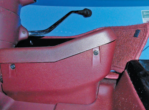
With the seven screws removed, the instrument bezel is free to come out. The gear selector arm however is in the way. So the parking brake is applied; the ignition lock turned to the first click, and the lever is pulled down into first gear. To obtain a bit more space, the steering wheel is tilted downward. Normally this would allow the bezel to be lifted out and set aside, but on this vehicle two aftermarket gauges have been mounted within it. Not a problem, there is ample wiring to these gauges allowing the bezel to be rotated clockwise enough to access the headlight switch as seen in Photo 22.
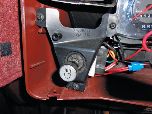
The headlight switch is mounted to a plastic bracket (see Photo 23) that is secured with three screws in the lower left corner of the dash. Removing these three screws allows the switch and bracket to be pulled out and away from the dash. Next I chose to remove the knob and shaft. This is done by fully extending it as though you had turned on the headlights, and then pressing the metal button on the bottom as is being done in Photo 24. While the button is depressed, pull the knob once again and it should exit the switch.
Now look at Photo 25 and notice the retaining collar holding the switch to the plastic bracket. There is nothing special about it, but you will need an extra-large screwdriver with a very fat blade. If you have any small pieces of scrap metal laying around, a section 1 ⁄8" thick x 3 ⁄4" wide will fit into the slot perfectly, and easily remove it.
From my tool collection an adjustable lens spanner tool from my camera repair days was used to remove it. This has two blades that can be positioned next to each other, or they can be slid up to 41 ⁄2" apart if needed. This is handy for removing a variety of switch collars. This collar isn’t very tight, so you can likely improvise with needle nose pliers. Open the tips until they bridge the gap, and give them a twist counterclockwise. Once it is initially loosened, you can spin it off by hand. With the collar removed, the plastic bracket is slid off and set aside. All that remains is to unplug the harness from the switch, and then put the new switch in its place. Some harness connectors may have “ears” similar to the dimmer switch connector that will lock it to the light switch. This one, however, does not, although it requires a bit of prying to free it. Photo 26 shows a couple of things; first notice the switch has a positioning tang that lines up with the notch in the bracket. Also, the lower mounting tab is broken, with about half of it remaining.
What If This Plastic Bracket Can’t Be Saved?
One of the top two tabs is OK, while the other has a hairline crack. The lower tab is broken and what remains is cracked. With the use of small washers to secure it, I think the life of this bracket could be extended, but let’s take a look at the options here.
A call could be made to the local Chevrolet dealer to check on availability of a new one. Possibly this flimsy bracket was used in enough other applications that it is still available. No doubt they broke frequently.
National Parts Depot (npdlink.com) is another option. They are a restoration partssupplier for many vehicles including Chevelle and El Camino. But a quick look in my three-year-old catalog didn’t show one, so a phone call or visit to the website would be in order.
There is always the used option, but the survival rate of small plastic parts in a salvage yard isn’t very good.
Next, we’ll make a new bracket for the switch, install the new headlight switch…and find that there’s still more work to be done.


