Rebuilding a 4-Speed Hydra-Matic, Pt. 3
![]()
There’s Some Intricate Work to Be Done at This Point. Then We’ll Reassemble the Unit and Install It.
EDITOR’S NOTE: LAST month we serviced 15 of the 16 basic units that make up this Hydra-Matic transmission. We’ll pick up here with the control valve assembly, a complex device with numerous components to consider.
Servicing the Control Valve Assembly
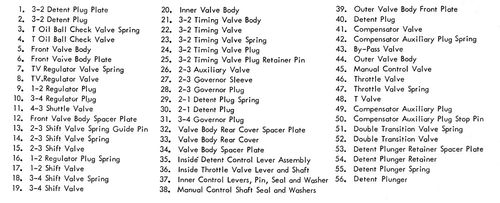
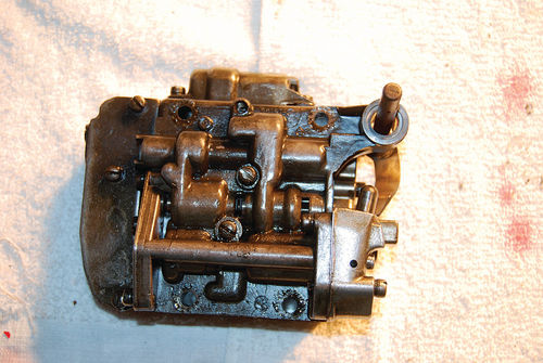
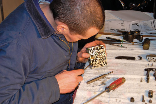
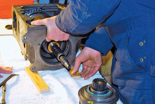
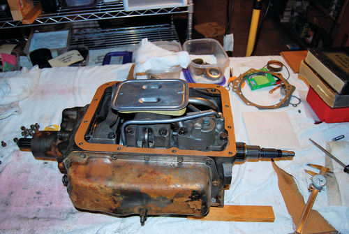
The control valve assembly (CVA) is the transmission’s brain and typically has 60+ intricate parts that have to be clean and in good condition. When you take off the side cover you’ll see the CVA. Unhook the speedometer cable and remove the CVA by moving it forward. If you have a 1949-50 unit, the control valve and oil delivery sleeve are pulled out a bit so the CVA can be turned counter-clockwise to clear the case. A CVA is delicate. Handle it with care. Don’t clamp it in a vise!
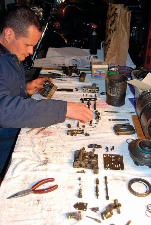
We laid all the little parts out on a couple of clean shop rags so they matched the illustrations in our repair manual. We were careful to cover any parts we weren’t using with a second clean rag. All screws must be kept in proper order.
Clean the valve bodies and plugs and keep them dry. Check for burrs, scoring or damage. Remove burrs with a crocus cloth and light oil. The valves in the CVA include throttle, shift, shuttle and regulator valves. The plugs include compensator auxiliary, detent, governor and regulator plugs. They all have sharp corners to prevent dirt clogs. Be careful not to round them off as you deburr them.
After the valves, plugs and valve bodies are clean and dry, check the shifter valve, governor plug and regulator plug to make sure there’s free movement in the bores and operating positions. You do this by seeing if they fall under their own weight, in their respective bores, when you shake the valve body slightly.
Check the fit of the throttle valve inside lever for looseness on the throttle shaft. Check the inside detent control lever for any looseness on the manual shaft. Check that the inside detent control lever pickup pin is tight in place and not excessively worn. Check the splines on the manual shaft and throttle valve operating shaft for wear or damage. Correct any problems. Support the valve body and control shaft so the throttle valve operating shaft, manual shaft and outer valve body won’t be damaged if the operating shaft pin is removed.
Use a small punch and hammer to tap the pin out. Remove the inside throttle valve lever, the detent control lever, the shaft seal and the washer from the outer control body. Replace any damaged parts and reassemble to the outer control body. While properly supporting the outer valve body and control shaft, drive a new operating shaft pin into place and check that all shafts move freely.
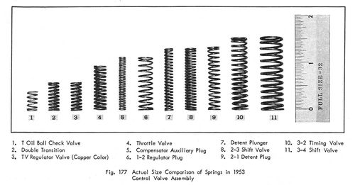
All springs should be strong and not distorted. Then check the surfaces of all valve bodies, plates and clean surfaces for cracks or scores and clean all the passages. Check all threads. Make sure the valve bodies are flat and not warped. A bad valve body means you need a new CVA. Check the “T” oil ball check valve for any damage or other roughness.
Servicing the Cone Type Reverse Unit (1951-Up)
During 1951 GM switched to a friction-type reverse in the Hydra-Matic. This involved the use of a cone clutch reverse mechanism that made the reverse shifts faster so a car could be “rocked.” A reverse inhibitor prevented reverse shifts above 10 mph, but allowed shifting into reverse at under 10 mph.
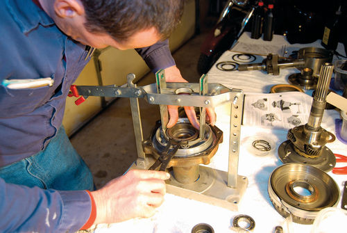
The friction-type mechanism had a reverse clutch stationary sleeve, a cone clutch piston, a cone clutch piston release spring and a reverse cone. There are 20 steps to remove the reverse assembly. Most important are removal of the reverse internal gear and stationary cone. Tool J-4670 helped disassemble the rear bearing retainer. It compressed the reverse cone clutch release coil springs to remove large snap rings. Universal compressing tools can be used today.
Sometimes the reverse piston comes out by pulling it straight up, but if not avoid twisting it because four dowel pins hold it in place. Instead, use compressed air blown into the smallest hole on the face of the housing. The rubber seal around the outside of the reverse piston and the inner circumference of the rear bearing retainer should be removed for replacement.
Remove the reverse stationary cone by using large snap ring pliers to expand the cone to just where it is removable. Take the flat clutch release spring and retainer out by lifting them straight up. Remove the snap ring that holds the reverse planet carrier to the output shaft and take the carrier off the shaft. Remove the carrier locating snap ring and steel and bronze thrust washers.
In the ’50s, parts were solvent cleaned. Today environmentally friendly cleaners do the same. Inspect and replace badly worn or damaged parts. The things to look for are worn ball bearings, gears with worn/damaged teeth, damaged splines, worn-out bushings, scored shafts or bearings, burning on the cone, collapsed piston coil springs, dirty oil seal grooves, loose or distorted dowel pins and roughness. Sometimes it’s hard to tell normal wear from excessive wear, so you may want to ask a professional to check. Clean all parts.
Re-assembly begins with holding the center gear with your left hand with the drive flange up. Install steel and bronze thrust washers in the recess in the drive flange. Pick the output shaft up in your right hand and put the end through the drive flange and center gear until the carrier bottoms on the thrust washers. Hold the drive flange and center gear tightly against the planet carrier to keep the washers in position. Place the output shaft and carrier on a bench on the carrier end.
Install the snap ring that locates the carrier so you can move everything. Install the carrier over the output shaft with the bronze drive gear downward, while meshing the pinions and sun gear. Be sure it bottoms against the carrier snap ring. Install a snap ring on the output shaft to position the carrier. Install the reverse clutch wave spring and retainer on the internal gear side of the reverse internal gear. The tangs that retain it should fit into the holes in the gear.
Install the reverse stationary cone on the reverse internal gear cone, being careful to spread it only as far as necessary. Put the large bronze thrust washer over the collar on the reverse internal gear and use Vaseline to hold it. A light coat of HMT fluid over the outside of the reverse cone piston inner seal will help it slide on the retainer hub with its lip side down. To check sealing, insert the piston (without a new outer seal) to test fit. Remove the piston and check the inner seal.
Install the outer seal with its lip facing the flat side of the piston and work the seal into the groove. Cover the outer seal with HMT fluid and put the reverse cone piston on the rear bearing retainer so the dowel pin holes are on the bottom of the piston, but don’t line them up with dowel pins in the rear bearing retainer.
A tool with an installing blade goes in the rear bearing retainer between the piston outer seal and the inner surface of the bearing retainer to fit the reverse cone piston into the housing. Do not damage the seal. Rotate the piston until the dowel pins line up with the holes and push the piston into place. Use a straight edge to make sure it’s seated. Lay it across the face of the piston and measure from straight edge to the face of the rear bearing retainer, 3 ⁄8- to 12⁄32-inch.
Put in the six reverse clutch release coil springs and press the retainer in with a compressing tool. Then install the snap ring and remove the compressing tool. Install the ball bearing in the rear retainer and gently tap into position. Install the large bearing locating snap ring in the retainer. Put the reverse internal gear and stationary cone into the rear bearing retainer. Compress the stationary cone by hand and position its keyway to line up with one on the transmission case. Have the output shaft standing on its planet carrier end. Place the rear bearing retainer over it and mesh the gears. Don’t damage the bushing or ball bearing.
Put the snap ring on the output shaft, locking it to the retainer. Install the speedometer gear. Put the gasket on the rear bearing retainer, install the stationary cone-to-cone lock key using Vaseline to hold it. Install the mainshaft and reverse assembly into the rear end of the transmission case, aligning the stationary cone lock key into the keyway machined in the case. Finally, align the rear bearing retainer bolt holes to the case and bolt up with bolts and lock washers.
Final Assembly
Start final assembly operations by mounting the transmission case upside down in a fixture. Install front and rear band adjusting screws and lock nuts. Put the pressure take-off pipe plug into the hole and torque to 15-18 lbs.-ft.
Next, fit planetary units to the front carrier by inserting the front carrier into the front unit drum and clutch drive plates and rotating the carrier to work it into position. Put the carrier in a fixture, then install thrust washers on the intermediate shaft, bronze on bottom. With tapered points of a new snap ring facing up, guide the ring vertically over the shaft and into the groove above the steel thrust washer.
Position oil delivery tube (parking brake bracket) on intermediate shaft of front planet carrier with oil rings on near end of sleeve down into front planetary unit. Compress lower oil rings with compressing tool and tap sleeve so it bottoms in bore of front unit drum. Install rear clutch hub snap ring and snap ring spacer.
Compress exposed oil delivery sleeve rings. Place the planetary unit over the intermediate shaft until it bottoms on the compressing tool. While keeping the rings compressed, release the handle latch and take slight pressure off the tool while pushing rear unit downward on oil delivery sleeve. Remove compressing tool and install the rear clutch hub snap ring. Both drums should easily rotate. If either drum binds it has to be disassembled so the problem can be corrected.
Next, install the planetary units. Position the center bearing cap on the oil delivery sleeve with dowel aligned and cast taper on bearing cap toward the front unit. Position the front band over the drum with its short anchor end over the band adjusting screw. We used plastic electrical ties to hold the band on. Guide the units into the transmission case, remove the electrical tie from the band and get the anchor end of the band to rest on the adjusting screw. Install the rear band on the drum the same way. Install a new center bearing cap lock plate. Make bolts finger tight. Then blow air pressure through clutch passages and listen for clutch application. Using a large screwdriver between the center bearing cap and rear clutch to prevent rear drum movement, remove the clutch hub retainer. Coat the rear clutch hub thrust washer with grease and put it in the counterbore.
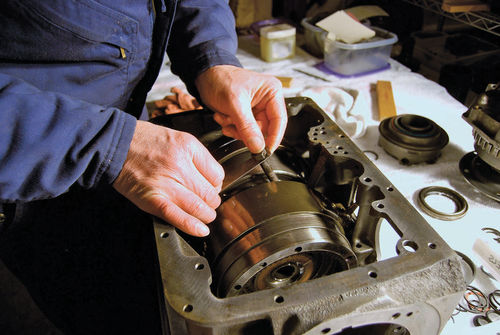
The reverse unit and mainshaft are installed now. If the original end play was off, you will need to select a washer that gives you .004- to .005-inch of end play. Grease the washer and stick it in the output shaft counterbore. Then, insert the mainshaft into the output shaft carefully, meshing the main shaft center gear with the output shaft’s planetary pinions. Insert the works through the rear of the transmission case, carefully guiding the mainshaft through the intermediate shaft at the front planet carrier. Align the keyways and rear bearing retainer bolt. At this point the rear bearing retainer won’t be tight against the transmission case.
Install the rear bearing retainer bolts, parking pawl support bolt and lock so they’re just started. Rotate the mainshaft to align the holes in the reverse drive flange and rear unit drum. Install six bolts and washers. When you have two bolts centered finger tight, remove the screwdriver you used earlier as a wedge. Holding the drum (there was a factory tool for this, but we used electrical ties) tighten the retainer bolts (not the parking brake pawl support bolt) to 10-13 lbs.- ft. Turn the mainshaft, output shaft and both drums to make sure all move freely.
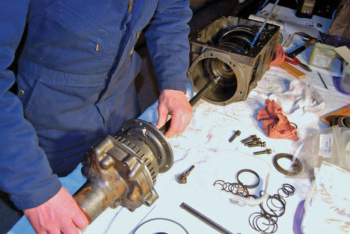
Install the front oil pump by positioning the thrust washer over the intermediate shaft and against the front carrier’s shoulder. Then install a new O-ring over the front pump body, against the cover. The front oil pump and drive gear fit over the intermediate shaft. Then install a washer and insert the attaching bolts, tightening to 10-13 lbs.-ft. Install the bronze, and then steel thrust washers over the shaft and against the front end of the drive gear. Lock in place with a snap ring. Lastly, tighten center bearing cap bolts at 40-50 lbs.-ft. Use large pliers to bend the lock tabs over the flats in the bolt heads.
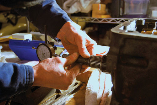
Check main shaft endplay before installing the rear pump and governor. The large round governor weight goes forward. Locate one attaching bolt to provide clearance for the pump and governor and install them, rotating the governor so its driven gear meshes with the bronze drive gear. Attach the pump case and tighten to 15-18 lbs.-ft. Install the rear pump discharge pipe in the pump passage.
A dial indicator is used to check governor and drive flange runout. If there’s more than .005 inches, remove the governor from the drive flange and install it 180-degrees over and recheck. Hopefully you won’t need a new governor.
Next, install front and rear servos by loosening (not removing) two front oil pump bolts. Then, insert the pump delivery pipe in the front pump and position the front servo with piston stem in the slot on the front band. The front oil delivery pipe must also align with the passage in the servo. While holding the front servo, align the rear oil pump discharge pipe with the passages in the front servo.
Move the front servo into position while guiding front pump delivery and rear pump discharge pipes into proper passages in front servo. Then just start the bolts and washers. Rotate the rear band until its ends are exposed. Put the rear band release spring in a recess in the end of the band and over a guide pin on the rear band strut. Turn the band until its end is against the adjusting screw.
Position the rear servo so it engages the rear band strut with the actuating lever of the servo, raise the front of the servo slightly and guide the oil transfer pipe from the front servo into the rear one. Push both servos into position in the transmission case. Install bolts and washers and torque to 23-25 lbs.-ft. Tighten the oil pump attaching bolts you loosened earlier to 10-13 lbs.-ft. Then install the oil pressure regulator in the case and torque the regulator valve plug to 49-50 lbs.-ft.
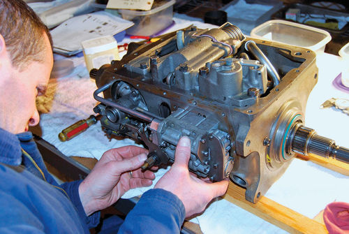
Install the parking brake cable and CVA by removing the parking brake pawl support bolt from the rear bearing retainer. Position the brake pawl in the case as far down as you can. With oil ring gaps on the governor tower up, place chamfered side of brake bracket oil delivery sleeve over the end of the governor tower and press gently into place, guiding the oil rings into position. Install reverse shifter crank roller on the brake pawl crank. Raise pawl into position, install bolt and lock and torque to 23-25 lbs.-ft. Bend one lip up against the bolt and two against the rear bearing retainer.
Next, install parking brake bracket attaching bolts, blocker piston stop pin retainer (on bottom bolt) and lock washer. Do not tighten bolts and leave brake bracket a half-inch away from the transmission case. Install reverse clutch oil pipe with “L” end in transmission case. Install two oil delivery pipes in parking brake bracket. Then position the pawl return spring over the inside groove in the oil delivery pipe. Hook the other end of the spring over the brake lever pin.
Install CVA and start four attaching bolts. Press control valve and brake bracket against case and torque bolts to 6-8 lbs.-ft. Insert short end of pressure regulator reverse oil pipe into control valve bore and put long end in case. Loosen two rear oil pump attaching bolts, align governor and tighten rear oil pump bolts and brake bracket to 15-18 lbs.-ft. Turn main shaft to rotate governor, which should turn freely. Go one-quarter turn. Recheck governor for freeness. If you feel binding, loosen parking brake bracket and/or rear oil pump and reposition until free. Recheck governor each quarter turn for one full revolution.
Remove the governor aligning tool. Install the governor oil delivery pipe. Turn the main shaft to rotate the governor one full turn, making sure the weights don’t hit the oil delivery pipe. The pipe should have the correct bend to provide clearance for the governor weights in their most outward position.
Adjusting the Bands
Your final job is adjusting the front and rear bands. GM service tools included a J-5071 rear band adjusting gauge and J-1693 front band adjusting gauge. We didn’t have these and asked Jesse Scheid of Scheid’s transmissions in Wisconsin Rapids, Wisconsin, for advice.
For an “on the bench” internal band adjustment, Scheid recommended snugging the adjusting screw then tightening it up 4-5 more turns. For the reverse band adjustment snug up and then tighten up the adjusting screw two more turns. Once the transmission is installed, several more adjustments can be done to the external bands. These are covered in shop manuals.
First, set the hand brake firmly and block the wheels to prevent the car from moving forward during adjustments. Start the engine and allow it to reach normal temperature. Connect a tachometer to the engine, place the lever in drive and adjust the idle to 700 rpm. The front band is adjusted by loosening the adjusting screw lock nut until engine speed increases to 900-1000 rpm. Then tighten the adjusting screw until the engine returns to 700 rpm. Again loosen the adjusting screw until engine speed increases and re-tighten slowly until engine speed returns to 700 rpm. Wait 30 seconds. If your engine speed increases, tighten the screw one tenth of a turn. Wait 30 more seconds and if engine speed increases again, tighten the screw one more tenth of a turn. Repeat this procedure until engine speed remains at 700 rpm for at least 30 seconds. Hold lock nut stationary and adjust screw 61 ⁄2 turns on pre-1952 models and 73 ⁄4 turns for later models.

To adjust the reverse band, repeat the first nine steps done for the front band, then put the car in neutral. While holding the lock nut, tighten the adjusting screw exactly two turns. Hold the adjusting screw stationary and tighten the lock nut, then reset the idle to achieve the factory recommended engine speed.
Taking It On the Road Again
The transmission is working well now. It no longer hangs up in first when cold and there are no leaks. In September many members of the Early Times Chapter of the Pontiac Oakland Club International stopped at Gunner’s Great Garage on their way to the Flathead Reunion in Red Wing, Minnesota. I drove from central Wisconsin to Red Wing with them, then crossed Wisconsin again, then took the car to the vintage races at Elkhart Lake. It ran fine all the way.
I think an expert could fine-tune the shifts even better than we did, but the 4-speed Hydra-Matic has many adjustments and we made most of them just right. I wish that I had the factory tool set but they are rare to find.
Editor’s note: Gunner’s Great Garage, in Manawa, Wisconsin, is a combination restoration and appraisal shop, art & photo gallery, and automotive gift/book store owned by the article’s author, John “Gunner” Gunnell. Visit gunnersgreatgarage.com.


