
Diagnose & Replace a Faulty Water Pump, Pt. 3
It’s Time to Install Our Replacement Pump… and, Wait a Minute, That Bolt Hole Isn’t Where It Should Be…
Editor’s note: Last month we went through a number of brackets, belts and hoses to get to and remove a faulty water pump. After that we went to the parts store for a replacement and now we’re ready to start putting things back together. We’ll begin this month with Photo 44.
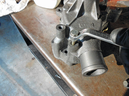
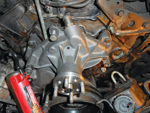
ONCE BACK HOME the new pump was placed in the vise, and the studs were installed. As Photo 44 shows, this pump is more universal, and has both a large and small bolt pattern for the fan and pulley. Make sure to verify with the pulley which you should use.
Next a 10mm wrench is used to make sure the rear cover plate is tight as is being done in Photo 45. You wouldn’t expect any problems with the threads in the face of this new water pump, but as you can see in Photo 46 I am not taking a chance. Running a 3 ⁄8"-16 thread chaser through the appropriate holes only takes a couple of minutes when the pump is sitting on the workbench. That’s much easier than if it’s installed on the engine and accessories have been attached.

Remove All the Old Gasket Material
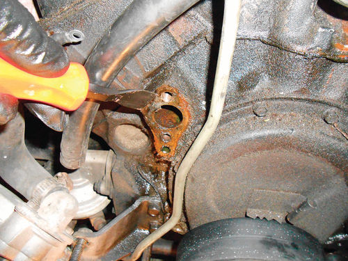
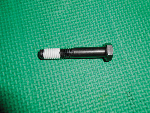
The new pump is ready to go, but the same can’t be said about the engine. Old gasket material remains on the mounting surfaces for the water pump and must be scraped as is being done in Photo 47. Should any of the old gasket material escape into the water ports for the pump, make sure to remove it. Again the 3 ⁄8"- 16 thread chaser is being used in Photo 48 to clean out the mounting threads in the block. The lower threads in Photo 48 go directly into the water jacket, so either wrap the bolt with Teflon tape as shown in Photo 49, or use gasket sealer if you prefer.
When it comes to installing the new water pump, many people no longer use gasket sealer, simply preferring to install gaskets on machined surfaces dry. Old habits are hard to break, and I still use a container of aviation Permatex; the choice is yours.
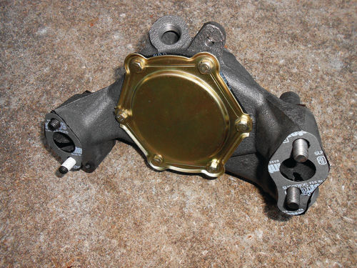
Photo 50 shows the pump ready for installation. Had this been an older Chevrolet engine that sported “Chevy orange” paint, I definitely would have painted the pump the matching color. This engine,however, is black and not very exciting, thus I lacked the motivation to paint it. Besides, the engine itself needs cleaning and repainting, but that will have to wait for another day.
It didn’t take but a few minutes to bolt the pump on, thread in the heater hose inlet and as Photo 51 shows, the pump is on. Of course there is still a long way to go before adding coolant. If any of the parts that have been removed are in need of cleaning, now is the time to do so.
Replacing the accessories will be in a slightly different order, starting with the power steering pump. Its belt fits into the first groove on the inside of the crankshaft pulley and doesn’t connect to the fan pulley, so it can be installed and the belt tightened.
Something’s Not Right Here…
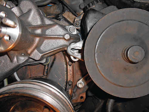
Reassembly seems to move along faster than disassembly; at least it usually feels that way…but not this time. The power steering pump was hung off the top-mounted pivot stud, and the stud on the rear of the pump was positioned into the low rear slide adjustment. To my surprise the front slide adjustment wasn’t lining up with the mounting threads in the pump. Take a look at Photo 52. The slotted mounting bracket was probably 1 ⁄2" too high. The upper rear slide adjustment (see Photo 26) wasn’t lining up either, although it was very close. Naturally time was wasted trying to line things up without any success. So let’s review the facts. The lower rear mounting stud is actually part of the power steering pump; the other three mounting points are determined by a mounting plate that bolts to the face of the pump, behind its pulley. This mounting plate is one piece of 1 ⁄8"-thick steel. Both of the rear slide adjustment slots are bolted to the block; are tight and secure, and there has been no change to the top pivot bolt mounting.

Could this new water pump casting be a bit off? I realized this was a long shot and highly unlikely, but certainly not impossible. There isn’t room for it to be off much anyway, but then it wouldn’t take much. A mounting boss that was machined slightly higher, as well as a mis-drilled mounting location could all add up to this 1 ⁄2". Had there not been a change in manufacturer, this thought would have never come to mind. After all, this was the sixth time this vehicle’s pump has been replaced over a 17-year period and there has never been any difficulty in the past.
I phoned the NAPA store to find out if my old pump was still there, and it was. A return trip was made into town, and the defective pump was purchased back from NAPA. They would, of course, refund the charge when the defective pump was returned to them. As opposed to going in screaming that the new pump from China was no good, I willingly confessed to the parts clerk I was most likely suffering from “Old Man's” disease, and that there were some comparison questions that needed to be resolved. Once back home an inspection was made for any obvious differences, but none could be spotted with the new pump still on the engine. A pair of new water pump gaskets had been purchased with the anticipation that the new pump would have to come off, and might be going back on. Once next to each other on the workbench the height of each mounting boss was compared, and they were identical. The next question was the threaded holes’ orientation, and how to accurately check it. The pump mounting boss is a through hole on both pumps, so my wife came up with the idea to place a sheet of 11" x 17" white paper on the top of the workbench, and then trace the casting with a pencil where it mounts to the block. While the exterior of the pump castings won’t be absolutely identical, they will be close enough to align one with the other for comparison. Next a transfer punch was dropped down through each mounting hole, and finally the mounting boss, leaving indentations in the paper. This pump was set aside, and these tiny dimples on the paper were dotted with a black Sharpie to identify them with that pump. The other pump was lined up with the pencil outline of the casting, and again a transfer punch was used. The pump mounting holes were dead on, while the mounting boss was off 1 ⁄64". This slight variation could easily be explained away due to the fact that the clearance holes (behind the threads) were different sizes on each pump, and required a different transfer punch. One was a snug fit, while there was a bit of wobble in the other. So the new pump wasn’t the issue. The old pump was even temporarily bolted back on the block just to satisfy me, but there was no difference.
At this point I was hoping my wife would wake me up and I would realize that this was all a bad dream. A visual comparison was made of the power steering pump and bracket with the one used on my 1987 El Camino, but nothing could be detected; it appeared identical.

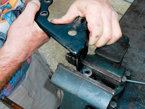
The decision was made to remove the bracket from the pump for inspection. To make life easier, the two hoses were disconnected and the pump was removed from the vehicle. The fluid was then drained from the pump. This also allowed the pump to be cleaned off in the parts washer, and then taken over to the workbench to remove the bracket. Three 13mm bolts secure the bracket beneath the pulley, and yes they can be loosened and removed with the pulley in place, although it’s a tight fit. With the bracket removed and cleaned, it alone was positioned on the engine. Nothing had changed, and I was still stumped. The bracket was removed, and I started to walk away with it in hand, and then I noticed the upper mounting arm of the bracket had a twist in it. While it looks all too obvious in Photo 53, believe me it wasn’t noticeable until the bracket had been removed.
About That Bracket…
In a flash, all became clear. This arm of the bracket had twisted when the top mounting stud rotated while trying to remove the nut. The torque being applied by the ratchet and socket actually caused this twist, which in turn decreased the distance between the two mounting points. This bracket is a thick piece of metal, but the upper mounting arm is basically flat, not having any curvature to reinforce and increase its strength. Photo 54 shows it positioned in the vise for straightening, and it was surprising how easy it was to do. It took several corrections to the bent arm, checking the fit each time on the engine until all finally lined up properly.
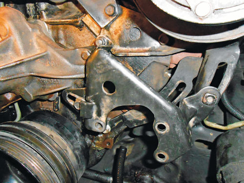
In Photo 55 all the mounting points are again lined up, and in the same plane. Note also in the photo that there is a 5 ⁄8" square nut welded to the right side of the bracket. This is what the outer slide adjustment bolt threads into, but it will also be useful when tightening the belt. The bracket was then removed from the engine and reinstalled on the power steering pump. The pump and bracket were placed on the engine. A new rubber O-ring was installed on the end of the high pressure hose at the pump; both hoses were then reconnected, and the pump reservoir was filled with fluid to the cold full line. There is air that needs to be bled from the power steering pump, and it’s accomplished by working the steering wheel back and forth several times through its entire range of motion. The vehicle will need to be running, so this will be done once the radiator has been initially filled. The new power steering belt was placed in the pulley grooves and a 5 ⁄8" eight-point socket is used on a ratchet to leverage that previously mentioned welded nut to tighten the belt as seen in Photo 56. While the ratchet is being pulled up to tighten the belt, the wrench on the opposite side is tightening the slide adjustment bolt. If an eight-point socket were not available, an open end wrench can usually be made to fit into the space and perform the task. The remaining bolts were then tightened.
A few observations… You might wonder how something like a bend in a bracket could be so difficult to spot, and become such a troublemaker. There were several factors involved: It was not at all obvious when the bracket was still on the pump; I couldn’t see it even when comparing with a known good one on a similar vehicle. The bracket was constructed of thick metal so it seemed like it couldn’t be an issue (at least in my mind at the time). There also was the seed of doubt with regard to the quality of the pump casting. Had it been from the same manufacturer as the previous pumps from NAPA, I wouldn’t have had any question.
At times it’s easy to get wrapped up in the event, and what seems so simple and obvious a day later isn’t even imagined when in the midst of it all.
So what could be done to avoid this situation? During the reinstallation the stud was securely tightened and a drop of blue thread sealer was placed on the threads. A washer was also placed in between the bracket and the nut. But most importantly, when removing the power steering pump, loosen the top pivot bolt first, prior to loosening any of its other fasteners. With all the other mountings secure, should the stud try to rotate as this one did, the bracket won’t be able to move, and should this arm twist, you will see it. There may still need to be some straightening, but certainly not as much. So instead of doing the procedure as was stated during the removal of the pump; leave all the bolts tight and in place until the top pivot nut has been loosened. Lesson learned.
Let’s Deal With a Few Hoses
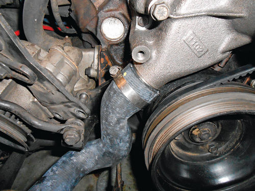
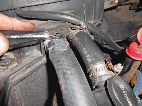
Now is a good time to put the lower radiator hose on. Access to the pump and lower radiator hose neck won’t get any easier than it is now. A new hose is being installed in Photo 57, and to make it slide on with less of a fight, a spray bottle with soapy water is used to coat both ends of the hose and the necks holding it. The original orientation of the hose clamps was noted before they were removed so they could be positioned in the same location. The clamp on the radiator side is positioned so that the screw head is facing straight up, and is on the side of the neck next to the frame rail as seen in Photo 58. This hose was an exact fit, not requiring any shortening. Many hoses will have cut lines on the end, typically marked “A”, “B” & “C”, with corresponding lines. No parts clerk has ever advised me that for my application it shows to cut at line A, B or C. So when a hose is too long to fit, I study the bends to determine where the added length is. If there are cut lines only at one end of the hose, then you can usually assume that’s the only end they want you to shorten.

Cut and shorten the hose gradually, making the first cut at the first line, and then test the fit. Once cut, the hose is non-returnable, so if you remove too much, a new hose will have to be purchased.
Both heater hoses are being replaced as well. Photo 59 shows the 5 ⁄8" outlet on the front corner of the intake manifold, and is somewhat hidden by the top alternator bracket. Removing the clamp and cutting the hose off is all that’s needed if you know you are replacing the hose with a new one. This vehicle uses straight heater hose sold by the foot, like many vehicles of the day. For my Caprice 3' of ¾" and 2' of 5 ⁄8" heater hose were purchased. Assuming that each old hose fit properly; stretch it out next to the new one and cut to the proper length.
Photo 60 demonstrates the safest way to remove a hose from the heater core. Actually take a slice out of the side of the hose, exposing and cutting through the reinforcement cord. The hose will lose its ability to squeeze and hold onto the connection. If needed, take another “slice” off to the side of the first, further weakening the hose, and then remove it. It’s not uncommon for the hose to simply stick to the heater core tubes even after making a slice or two. If it still won’t come off with a gentle twist, then make a straight cut into the hose in this shaved area. If possible, avoid cutting directly against the core’s brass neck, and instead glance off to the side of it. The hose should then finally surrender. Sometimes there will be some bits of rubber that remain bonded to the core’s inlet and outlet. Simply use a knife to scrape them clean. The heater core has probably the most delicate fittings in the cooling system, so you don’t want to wrestle with them. I don’t mean to make this sound like it’s brain surgery, but if you take a gently cautious approach, you will avoid the possibility of damage to the heater core. When replacing the heater hoses, soapy water can again be used to make them slide on easier.
Now all the hoses have been installed with the exception of the upper radiator hose and the ¾" heater hose to water pump connection. This heater hose will remain off until the alternator bracket is replaced, and the upper radiator hose will be the last item to be replaced once the fan shroud is back on.
Turning to the A.I.R. Pump
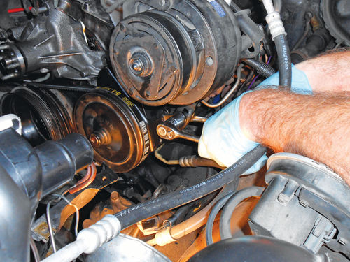
The bracket for the A.I.R. pump is next. Bolt it onto the face of the water pump finger tight, with the stud at the bottom, and the bolt above it. If there is any question with regard to proper positioning of the bracket and bar, reference Photos 41, 40 and then 39. Retrieve the alternator from the pile of parts; position it above the A.I.R. pump bracket and reconnect the battery positive wire to the rear (see Photo 38). Think about how it will be positioned once the belt is on, and have the wire exit straight down and then tighten the nut. There is easy access to this 10mm nut even when the alternator is tight and in position, so it can be repositioned later if needed. There is a plastic insulator cap that protects this battery positive wire from accidental grounding. It just snaps into place over the 10mm nut. Some vehicles will have a rubber boot that will remain on the wire. That type of insulator simply slides up the wire and covers the connection. Next plug the wire connector into the side of the alternator, and then line up and thread in the pivot bolt finger tight as is being done in Photo 61. Its top bracket connects to three points: the slide adjustment for the alternator, the face of the water pump, and the top of the intake manifold (see Photo 35). With all the alternator mounting bolts threaded in, tighten the bolts connecting the top bracket to the intake manifold and the face of the water pump. Now go back and tighten the A.I.R. pump stud and bolt holding its bracket to the face of the water pump, and then replace the lower pivot bolt with the bar that bridges over to the stud. Tighten the nut securing the bar to the stud, but leave the pivot bolt finger tight for the moment. The belts need to be in place before these final bolts can be tightened, and before they can go on, the pulley and fan must be replaced as shown in Photo 62. Slide the pulley onto the studs, and then position the fan on the studs and center boss of the water pump. Next replace the nuts and tighten them as best possible, they can be tightened fully once all the belts are on.

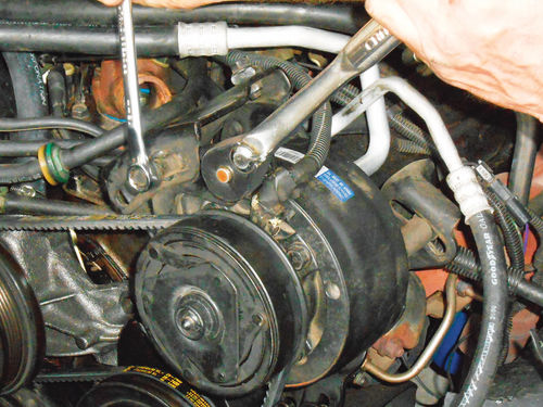
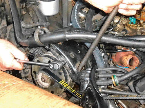

The air conditioning belt travels over the water pump; crankshaft; and the power steering pulleys, and it is the next to go on. Due to the large size of the clutch in front of the pulley on the AC compressor, start by positioning the belt there first, and then place it onto the other pulleys. Use a 1 ⁄2" drive ratchet in the corresponding 1 ⁄2" drive hole to leverage and tension the belt as is done in Photo 63. At the same time a 15mm wrench is used to tighten the front slide adjustment, followed by the rear one just opposite it. The ratchet can be removed, and the final slide adjustment (Photo 22) and the pivot bolt (Photo 23) can be tightened. The alternator belt is next. The belt is positioned in the proper pulley groves, and a pry bar is used to leverage the alternator in Photo 64, and then the slide adjustment is tightened. A good way to judge the belt tension is to grab onto the alternator pulley/fan as I am doing in Photo 65 and try to rotate it. Tighten the belt just beyond where it can no longer be rotated by hand, and then secure the slide adjustment bolt, followed by the alternator pivot bolt located at the bottom (see Photo 61).
A couple of notes here; the pry bar is positioned through the opening in the bracket, and is leveraged against the forward-most part of the alternator casting. This is the area of the alternator casting just behind the pulley. The forward edge is strong, and safe to use as a point of leverage. The center of the alternator, behind where the casting splits in two is thin, and will break easily.
Next we’ll install the A.I.R. pump and mix the proper coolant solution for our car.


