Diagnose & Replace a Faulty Water Pump, Pt. 2
We Need to Remove the Pump That’s Currently On the Car. But This Is an ’80s Model, and There Are Numerous Brackets, Belts and Hoses In the Way.
Editor’s note: Last month a groaning water pump led to some tests which showed it’s time for a pump replacement. That, in turn, led to some system flushes and the removal of the thermostat for improved flushing. Now we’re preparing to remove the old pump.
Rinse Once More; Then Replace the Thermostat
Fill the system again but this time with just water and replace the radiator cap. Run the engine with the heater on for about 10 minutes, then let the engine cool and repeat the same draining procedure. If the system was particularly rusty, the rinse procedure can be repeated.
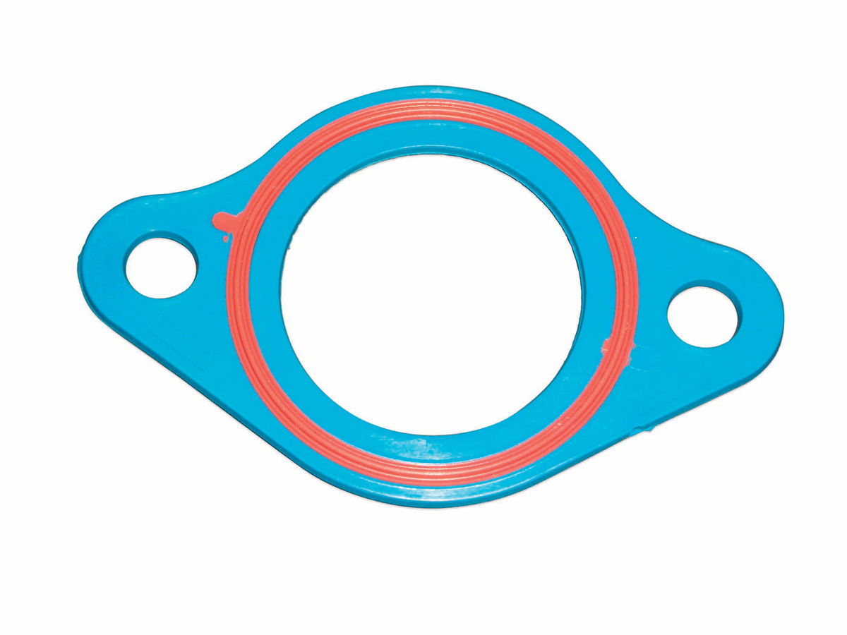
Next up is replacement of the thermostat. When replacing the thermostat, pay close attention and make certain it remains positioned in the recess. If there have been previous problems with coolant seepage around the thermostat housing, consider using a special gasket made by Fel-Pro such as the one shown in Photo 13. Instead of the thin paper-style gasket, this one is made of plastic, 1 ⁄8" thick with a raised silicone seal on both sides and it’s applied dry. This will compensate for distortion in mounting surfaces and eliminate seepage. According to the package, this Fel-Pro (#35562T) gasket fits GM V-6 & V-8 engines for 1955-95, and is certainly made for other vehicles as well.
On any vehicles where steel bolts are threading into aluminum, it’s a good idea to apply a small amount of anti-seize compound to the bolt threads. When tightening the thermostat housing, go back and forth between the two bolts and tighten them gradually and equally. This thermostat was replaced less than a year ago, so it will be reused. Normally it’s replaced on a five-year interval when the cooling system is flushed and maintained.
Organize Your Bolts

As bolts are removed, they often should be threaded back into the locations where they came from once the component itself has been removed. Some bolts may be of slightly different lengths in certain locations or some may have a metric thread. So threading them back into place will help eliminate questions of which bolt goes where. Even bolts that thread into the face of the old water pump can be reinserted. Just switch them over to the new pump once you have it in hand.
A large piece of corrugated cardboard also works well as a bolt organizer. For example, make a large sketch of the components on the front of the engine that will be removed. As bolts are taken out, poke small holes in the locations on the cardboard where they go, and then push each bolt into the appropriate location. You also can make notes on the cardboard indicating a bolt that is positioned from the rear. The power steering pump and A/C Compressor are both good examples. If a group of bolts are all the same length then that can be noted as well. Taking notes now can eliminate confusion later, and if the project gets stretched out over several days or weeks, you will be glad you did.
A digital camera is another great asset. Take your own reference photos as you go along, and stop to make notes when you feel it necessary.
On the other hand, if you should happen to know every nut and bolt on a first-name basis, then simply collect them all in a larger container.
Removing the Water Pump
Start by disconnecting the negative battery cable. With the cooling system drained, remove both the upper and lower radiator hoses. The upper hose should be fairly easy to remove as it was taken off to remove and replace the thermostat. The lower hose connection to the radiator also will be easy, but the end connected to the water pump will be a bit more reluctant to come off. Once the hose clamp is loosened, slide it farther onto the hose, and then use the pick tool we used in the previous article to break the bond between the hose and the pump. Then twist and pull the hose off the pump. It’s not unusual to work on the lower hose both from over the fender and from underneath the vehicle.
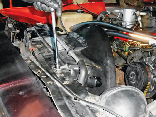
Next is the fan shroud. It’s constructed of an upper and lower section. Removing a total of eight bolts with a 10mm socket and ratchet as is being done in Photo 14 will allow removal of the upper half. It might be possible to do the job without removing it, but it only takes a few minutes and it makes everything easier, including taking the photos mentioned above. The high pressure air conditioning line travels across the top. There are two plastic retainer rings that can be popped open to disconnect this from the shroud. With the bolts removed, and the aluminum line unclipped from the top, the shroud can be slid toward the driver’s side, and then rotate the end inward toward the engine. This will allow it to slide out completely. Handle the air conditioning line with care, aluminum will bend easily.
With that out of the way, the vulnerable radiator core is now visible. Get a section of corrugated cardboard large enough to protect the core, and place it in front. This is the best insurance you can have to avoid accidental damage to the core. You think nothing could ever happen, but somehow it does. Another word of caution; you may find yourself in positions where you want to lean on things under the hood for support while performing some of the upcoming tasks. Know what you are leaning on. Alternator or air conditioning brackets are good; air conditioning hoses with aluminum manifolds are not a good choice. There also is plenty of plastic in the engine compartment on the fender wells, and it will do just fine as long as no one leans on any of it. As you might suspect, this insight on plastic comes from experience.
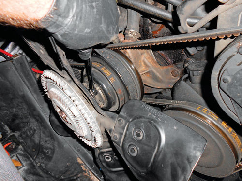
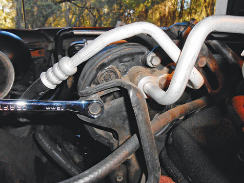
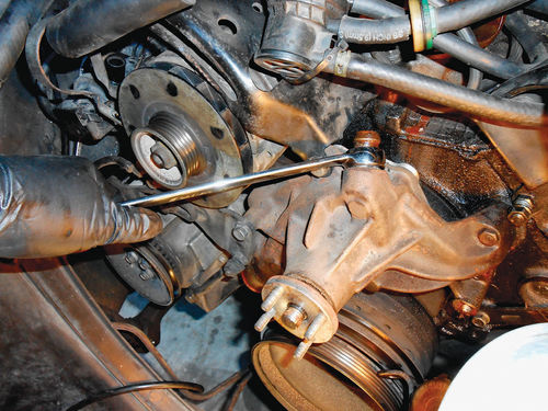
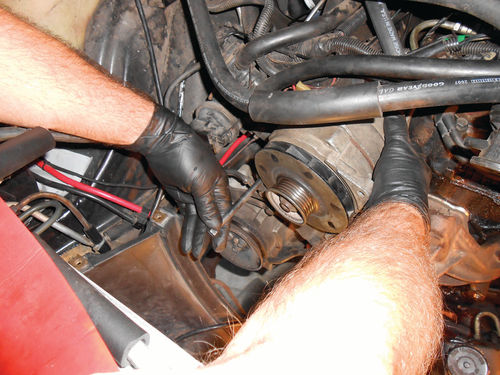
Next remove the water pump’s fan. This opens things up making it easier to see what’s ahead of you, and component removal is easier. While the belts are all connected and snug you won’t have any worry about the fan trying to rotate. A long 1 ⁄2" wrench is used in Photo 15 to remove the four retaining nuts. The spacing between the fan blades varies, so there are some areas that will give you easier access than others. Note that round, finned aluminum part in the center of the fan. This is the fan clutch. It engages and disengages the fan as the name implies. We will discuss how to check its operation at the end of this series, once the new pump is in place.
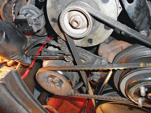
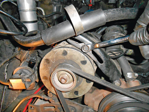
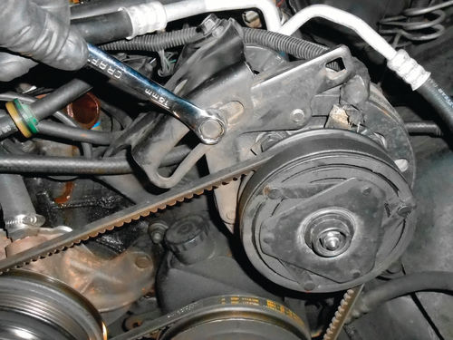
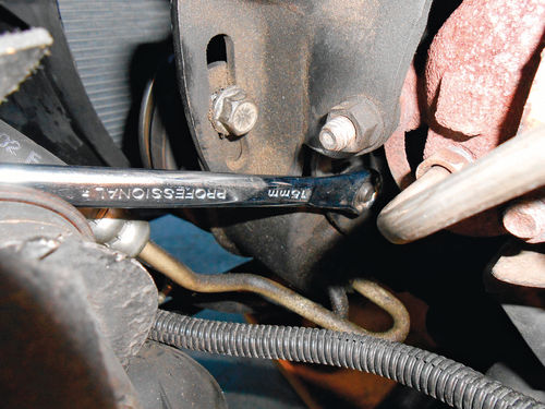
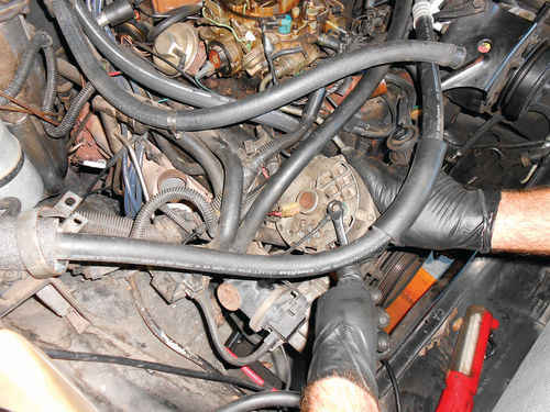
With all the nuts removed, the fan is slid off, and set aside, while the pulley remains on the studs. There are four belts needing to come off, and the A.I.R. (Air Injection Reactor) pump is the first in line. Its belt is the only one that doesn’t connect to the crankshaft pulley; it connects only to the water pump pulley. A 13mm wrench is used to loosen the slide adjustment bolt in Photo 16, and then again on the lower pivot bolt in Photo 17. Just a light tug on the belt and it will pull the pump inward, and the belt can be removed. Ultimately the alternator, power steering pump and A.I.R. pump will all be removed, but some brackets are shared between components, and sometimes the belt for one accessory may block clear access to bolts for other accessories, so I choose to remove all of the belts first, and then remove each component.


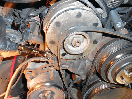
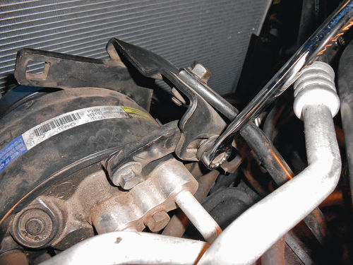
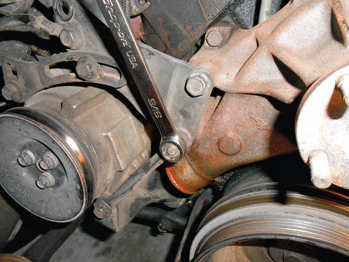
The alternator’s top adjustment bolt (Photo 18) can be loosened with a 13mm or 1 ⁄2" wrench. Photo 19 shows the lower pivot bolt being loosened with a 9 ⁄16" wrench. Notice that the alternator belt has loosened on its own due to the weight of the alternator reacting to gravity. The belt can now be removed. The air conditioning compressor won’t need to be removed, but its belt removal will require loosening four bolts, all with a 15mm wrench or socket. The first one is the top front slide adjustment as shown in Photo 20. There are two more slide adjustment bolts on the rear. One is exactly opposite the bolt just loosened on the front, (see Photo 21), and the other is located at 9 o’clock (as viewed from the driver’s seat), shown in Photo 22. Even with these three adjustment bolts loosened, you will still need to loosen the pivot bolt located at 6 o’clock as shown in Photo 23. Before attempting to remove the A/C belt, loosen and remove the metal loop that retains the air conditioning hose on top of the alternator bracket visible in Photo 24. Doing so will allow the hose to move freely when you pull on the belt to remove it. A 1 ⁄2" wrench will remove the bolt, and the metal loop can remain on the hose. Now grab the air conditioning belt and give it a gentle pull. This will pull the compressor inward, and the belt can be slid off.
The pulley can now be removed from the water pump and set aside with the collection of other parts.
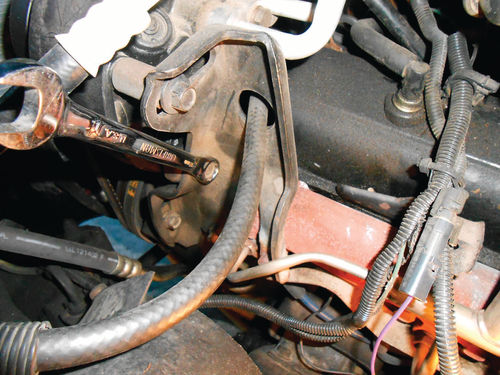
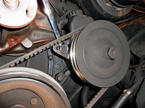
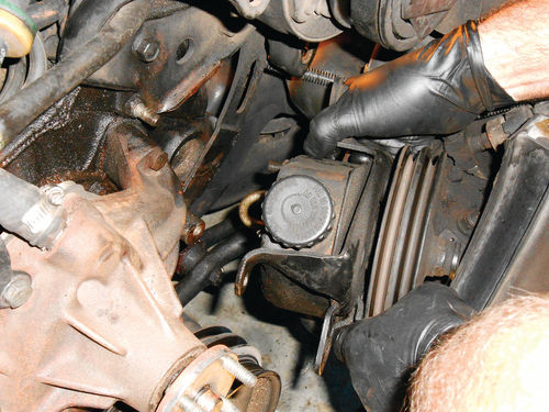
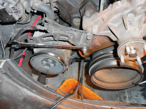
The last belt to be removed is with the power steering pump. That also will be the first accessory to come off. There are a total of four fasteners securing the pump, two on each side. This time when a bolt or nut is loosened, it will also be removed. Start with the front slide adjustment bolt shown in Photo 25. This bolt threads into the water pump, and a 9 ⁄16" wrench was used to remove it. Moving to the back of the pump and using the same wrench, loosen and remove the outermost slide adjustment bolt seen in Photo 26. Next is the lower, innermost mounting nut. Photo 27 seems to make its access appear more open than it actually is. I started by using this long 15mm wrench with the offset positioning the wrench forward, just clearing the front of the upper control arm. Movement is limited in this area, so once it was initially loosened a stubby 15mm wrench was substituted until it could be removed by hand. An offset ratcheting box wrench would also be a good option for the task. There is one mounting remaining, the pivot stud located to the left of the fill cap in Photo 28. A 9 ⁄16" deep six-point socket with an extension was used here. When initially trying to break this nut loose, the entire stud was trying to rotate back and forth. In turn it was moving the pump back and forth as well. On the engine side of this bracket the stud has a 9 ⁄16" nut secured to it so it can be tightened, removed or held in place. Unfortunately there isn’t enough room to fit an open end wrench onto the nut to hold it. I decided to replace and tighten the rear slide adjustment bolt (see Photo 26) to secure the pump until this nut was loosened. I chose this mounting because it was easy to access, and is almost opposite the pivot stud being worked on. A 3 ⁄8" pneumatic “butterfly type” impact tool was used to see if it might work some magic in removing this stubborn fastener, but without success. The ratchet socket combination finally broke the nut loose with a loud pop, and there were no casualties incurred, or so I thought. With the nut removed, the bolt was again removed from the rear, and as Photo 29 shows, the pump was slid off, allowed to rest between the steering box and crankshaft pulley. While the power steering pump is off, it’s a good time to inspect the hoses. The hose that has metal tubing crimped to its ends is the high pressure hose. If you decide to replace it, you will want to use a 5 ⁄8" flare nut wrench when removing it. Study and make note of its orientation before you loosen any fittings. And note that this high-pressure hose uses rubber o-rings on the ends. The other hose is the return hose. This is a low-pressure oil hose that can be purchased by the foot. This is the same type hose that would be used with an aftermarket transmission cooler.
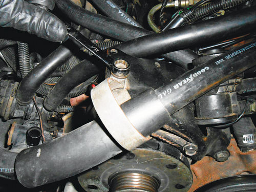
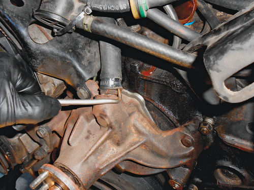
Now is a good time to remove the heater hose from the water pump. Loosen the hose clamp as shown in Photo 30, and then slide it up the hose so it is out of the way. Photo 31 shows how handy this cotter pin tool is for removing hoses. The heater core hadn’t been flushed on this vehicle, so the hose was very definitely bonded to the steel inlet neck. Once it was pried off, I realized the hose was due for replacement.
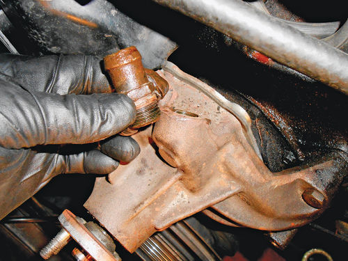
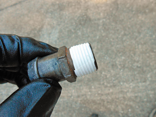
While the pump is still bolted to the block, a 7 ⁄8" wrench is used in Photo 32 to remove the heater hose neck. Photo 33 shows the inlet removed. Photo 34 shows the fitting after being cleaned up, wrapped with Teflon tape, and ready to be installed in the new water pump. Some people prefer to use gasket sealer on these threads, the choice is yours. The top alternator bracket is next in line. Remove the slide adjustment bolt from the alternator, and then use a 9 ⁄16" socket to remove the one bolt from the face of the water pump, and the other on top of the intake manifold seen in Photo 35. The bracket can now be lifted off and added to the collection. Note there also is a ground wire connected to the bolt on top of the manifold. Make certain it’s in good condition, and to keep track of it, place the bolt back through it and secure it to the manifold by hand. This way it’s less likely to accidentally be overlooked during reassembly. Photo 36 shows loosening the alternator’s pivot bolt with a 9 ⁄16" wrench. Once free of the threads, the bolt can be slid out as is being done in Photo 37. In some instances the bolt may be too difficult to rotate and remove by hand. If you are using an air ratchet to remove the bolt, this won’t be an issue, otherwise grab the head of the bolt with a pair of locking pliers and carefully twist and pull on the bolt at the same time. Remember to be careful so it doesn’t pull out abruptly and accidentally strike the radiator. At this point there is nothing holding the alternator in, just two wires, and the squeeze of the A.I.R. pump bracket on its pivot. The wire that plugs into the side of the alternator is easily removed by squeezing the small lock tab, and then pulling it free. Rocking the alternator back and forth a bit should free it. If it puts up too much of a fight, loosen the bolts of the A.I.R. pump bracket below it on the face of the water pump. When the alternator is lifted out, a 10mm ratcheting box wrench is used to remove the battery positive wire from the rear in Photo 38. The alternator is now free to set aside.
The A.I.R. pump is the last accessory attached to the water pump. A 9 ⁄16" wrench is used to remove the nut from the lower mounting stud on the face of the water pump in Photo 39. Photo 40 shows using a 13mm wrench to loosen the pivot bolt. When it’s free of the threads, slide it out, and slide the bar off the stud that bridges between the two. Pick up the 9 ⁄16" wrench again and remove the stud as seen in Photo 41, and then the bolt just above it. The pump and bracket can be positioned off to the side in the engine compartment, so it’s out of the way.

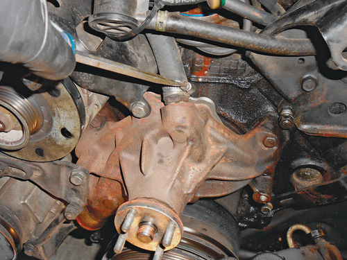
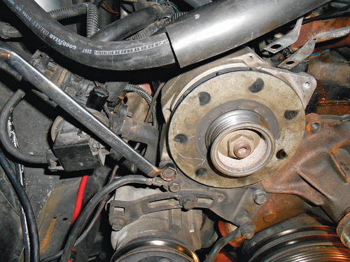
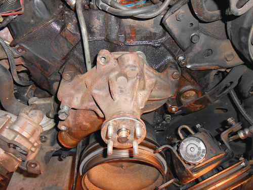
With everything removed we have finally reached the water pump as seen in Photo 42. With all of the accessories off its simplicity somewhat resembles a 1955 Chevrolet with a 265 CID engine. I realize that the pump casting is different, and has mounting bosses on it that they never dreamed of back then, but this less-cluttered look has a strong resemblance to decades gone by.
A 9 ⁄16" socket on an extension is the best choice to remove the four bolts securing the water pump to the block. Before completely removing the last bolt, make certain its bond is broken with the block. If not, give the pump a bump or tap with a block of wood or hammer to free it, and then remove the bolt. Note these bolts are all the same length on this application.
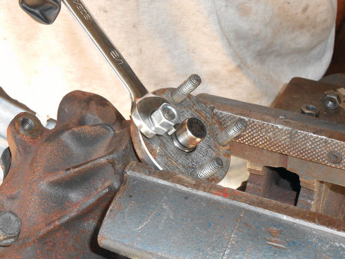
The final step on this old pump is to remove the fan mounting studs. This is easily accomplished by first securing the flange of the pump in a vise so it won’t rotate, and then threading two ¼-20 nuts onto the same stud and tightening one up against the other. Use a 1 ⁄2" wrench and rotate the lower nut counterclockwise as is being done in Photo 43 to thread out the stud. To install the studs on the new pump, use the nuts in the same approach, but this time rotate the upper nut clockwise. A dot of blue thread sealer (Loctite) can be used to secure the studs to the flange.
With the pump removed it was time to call NAPA to see what was in stock, and what needed to be ordered. The water pump has a lifetime warranty, so when calling I gave them the part number, but the parts clerk advised me that the part number was no longer any good. This was kind of a surprise, as it had never changed over the past 17 years. But he then advised me that they had the pump in stock, as well as all the belts and hoses that were on my list. Great!
Upon arriving at the store I asked the clerk about the change in the part number, and would it affect the lifetime warranty? He advised me that the part number change was due to a change in the manufacturer and the lifetime warranty would continue.
An inspection of the box told the entire story. The formerly USA-made premium water pump is now made in China. Was I surprised? No, not at all. Disappointed, certainly! However, it was nice to see that the Gates belts and hoses were still made in the USA.
Next, we’ll install the replacement pump…um…why doesn’t it fit?


