
Building ”Bowtie6,” Pt. 2
The V-6 Triumph Gets High-Performance Disc Brakes and a Steering Column While Viper-Red Paint Is Applied.
EDITOR’S NOTE: LAST month we started the build of “Bowtie6,” a 1972 Triumph TR6 whose new name came from the 3.4-liter Chevy engine installed by the owner as part of the project. This time we’ll continue with the suspension, then take a look at the brakes and get into some body work.
There were nine images in the first installment, so we’ll start here with Photo 10, the fully assembled rear suspension.
Suspension Work (continued)
As we said last month, each of the rear coilover shocks attaches to the frame on a special adjustable perch. The other side of the coilovers is attached to the control arms on a special mount that was welded in place. Basically, the bottom of the control arm where the spring normally goes was removed and this allowed for the proper fitting of the coilovers. (See Photo 10.)
Having relocated the coilovers to the area previously used by the original springs, the tabs on the control arms used for the lever shocks were freed up and used as mounts for the rear sway bar. The bar is mounted through the frame via two bearings and on either end of the bar are two arms that attach to the former lever shock mounts. All this is, of course, adjustable. This design turned out to be very simple yet effective.
The front suspension also was upgraded. A set of lowering springs from Good Parts was installed and this, along with a few other tricks, lowers the front stance by about two inches. The front shocks are Spax adjustable and all bushings were replaced with ones made of Polyurethane. The stock front sway bar remains although it is mounted on Polyurethane bushes too.

The steering rack is mounted to the frame via a pair of Good Parts solid aluminum steering rack mounts. The mounts are shaped to fit the rack perfectly and give a very solid feel. The rack does not move due to flexing of the bushes. Sure, there is a little road shock transmitted up the steering column but this is easily solved with a shock absorbing adapter (more on this later).
Finally, the rear control arms use Good Parts adjustable control arm brackets. These nifty little devices allow a very easy adjustment to the rear suspension and makes dialing in negative camber a very quick and easy task.
Racing Brake Parts Installed
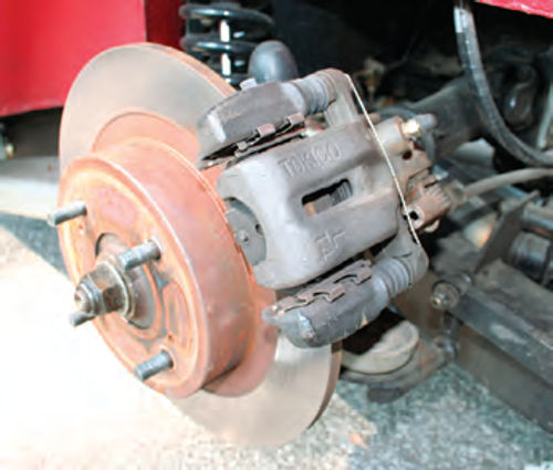
The original front calipers have been replaced with a pair of billet, lightweight Wilwood four-piston racing calipers normally fitted to Sprint cars (Photo 11). They are mounted using specially designed adaptor plates, and safety wired for added peace of mind. The rotors are stock Triumph units. They are cheap and easy to replace and require no modifications to fit. Some folks use vented rotors from Toyota—the decision was made not to use these because of the extra unsprung weight. Unless the car is driven extremely hard, this extra weight is not really needed.
The original Triumph rear brakes were drums, and as no modern high-performance car uses drums, the rear brakes needed to be redesigned. Once again, special adaptor plates were made and a Nissan 280ZX caliper has been mounted on each rear trailing arm. Basically, a plate was made very similar to the plate that held the original brake shoes, except it is made to accept the new calipers. Nissan 280ZX rotors have been used to maintain compatibility with the lug bolt pattern. The calipers were selected because they provide a very easy way to adapt the hand brake. A small adaptor was made to mate the original hand brake cables and this works using the original lever inside the car (Photo 12).
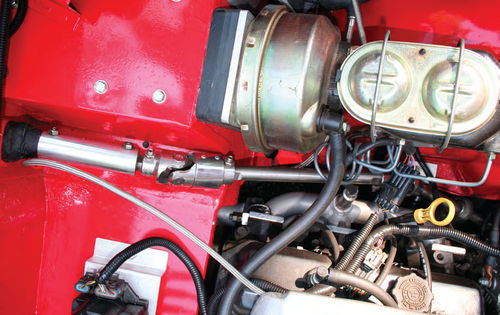
Installation of the new calipers called for a new master cylinder. The original master cylinder had a small bore and we needed something with larger volume. So, a master cylinder and booster from a Corvette was adapted to the Triumph firewall. Not only are these plentiful but they also are relatively inexpensive (as opposed to the Triumph units).

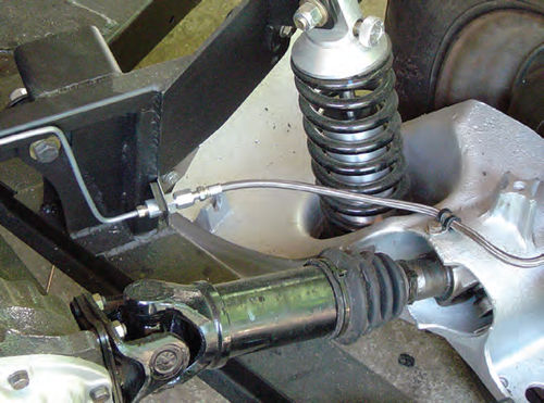
The entire braking system has also been upgraded with new hand-bent, custom cut and flared stainless brake lines. On each of the four corners, Teflon-lined braided steel lines connect the hard lines to the calipers (Photos 13 and 14). Finally, a Wilwood proportioning valve was installed and this came in very handy in balancing the grip of the front vs. rear calipers. With a little work, the brakes have been set up so the rears are nicely balanced with the front ones.
Wilwood street brake pads are used on the front, and a Kevlar/carbon pad is used on the rear Nissan calipers. This combination gives a very solid feel and the car stops very nicely with very little fade and excellent balance.
Welding Some Patch Panels
The original body was in very good shape; however, I wanted to ensure a proper preparation for paint. So, all body panels were removed and inspected.
Some small amounts of rot were spotted on the floorboards but they were easily repaired with small patch panels that were TIG welded in place. These patch panels were made from sheet metal and shaped with the aid of a PULLMAX shaping machine and formed to match the rest of the floorboard. The patch panels are so well-made it is hard to tell they were not factory original (Photo 15).
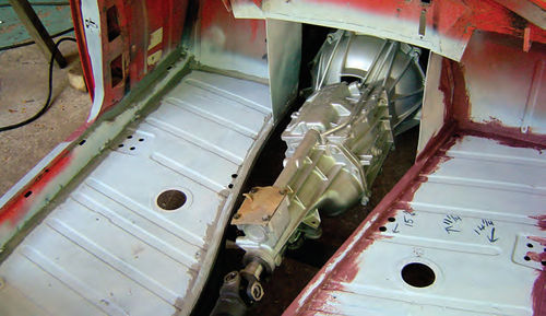
The new engine was mounted as far back as possible to help weight distribution, and that required some minor work to the firewall. Since the original battery box was rusted, that area was replaced with a new design that allowed the mounting of an all-aluminum transmission tunnel to the firewall from inside the car. The footwell area was boxed in and this also gave a little more room for the headers to fit properly.
Photo 16 shows the new boxing as well as two square tubing rods welded to the inside of the floorboards. The square tubing ribs help hold the new aluminum transmission tunnel and also helps to strengthen the floor of the TR6.
Every seam on the body was covered with 3M Brushable Seam Sealer. The body shell was also turned upside down, mounted on sawhorses and, after we had primed the belly, we applied an epoxy based bedliner material commonly used in pickup beds. This material, called Gator Guard, is extremely tough and provides a good barrier against water and the elements. At any rate, a cousin of mine had used this material before with great success so it wasn’t something new to me. One thing to keep in mind is that once mixed, you don’t have a lot of time to waste. The stuff sets up rock solid so one must apply it quickly. We used a small roller and in hard-to-reach areas, we used a brush. The biggest advantage is that it can be painted and the paint won’t flake off. After three years the underbelly of my TR6 is still solid and there’s no flaking. It does have a little bit of a texture but I could care less about that as long as the belly of the car is protected against water and debris.
After the inside floorboards, firewall, rear deck and transmission tunnel were painted, Dynamat Extreme was installed. This product consists of an adhesive backed rubberized material with a foil outer coating. This material is used in the auto sound industry as a sound deadener. It works very well.
Finally, the outside exposed sections of the tunnel and firewall were covered with a heat-resistant, self-adhesive thermal blanket. This keeps radiant heat away from the pedal box and passenger’s side footwell. The end result is a very comfortable experience for the driver as well as the passenger.
The Steering Column
The steering column on Bowtie6 is unique—it had to be to fit in the modified engine bay layout. With the addition of the V-6, the headers were in the way of the stock steering column. To solve the problem, a bearing was mounted on a special plate bolted to the frame. A new stainless steel rod was cut and fit to length and adapted to the steering rack.
The ends of the stainless rod were shaped into a “Double D” and Borgeson joints were used to allow for free movement (Photo 17). One of the Borgeson joints contains a special rubber damper to absorb road vibrations picked up by the solid mounts on the steering rack. Both of these Borgeson joints are stainless and not only look good, but they perform equally well.

A special note: It is highly recommended that a rubber-isolated Borgeson joint be used in this type of assembly. Originally, the system had two non-isolated Borgeson joints. The problem with this was quite a bit of road shock was transmitted up to the steering wheel. Once the rubber-isolated joint was used, the shock was virtually eliminated.
An aluminum tube was machined and special bearings installed inside it. This allowed for a new rod to be mounted inside that is attached to the steering boss and ultimately to the steering wheel. This method of mounting the steering rack provided a lightweight and effortless solution. The original turn signal switch was adapted to fit inside a special handmade enclosure. It works as designed for the original steering column.
The original fuel tank was badly pitted and scaling had reduced the overall thickness of the walls of the tank. Sourcing a replacement tank did not make much sense because it, too, would be subject to rust in the future. So, a new one was made instead, out of aluminum. Special baffles were added inside the tank to keep fuel from sloshing and a return line was fitted to comply with the fuel injection requirements.
Below the tank rests a special adaptor plate that holds the Bosch high-pressure fuel injection pump and fuel filter. These are the same that are fitted to Jaguar XJ6s and provide the required inline pressure to satisfy the injection needs.
The battery needed to be relocated since the original battery box area now holds the coil packs that drive the spark plugs on the V-6 engine. So, a special aluminum box was made to hold an Optima Red Top battery in the trunk of the car. These batteries are not cheap,but provide very good cranking power and have a very long shelf life. The battery sits on the passenger side for better weight distribution. Both battery leads are high-quality copper welding cables. Yes, the same ones used on TIG welding machines with silver soldered lugs.
Since it would be a sad thing, indeed, to cover up the tank, two small aluminum covers were made to nicely finish the flanks of the tank. All the exposed aluminum was sprayed with a clear coat to give it a nice shine and make it very presentable. Finally, black carpet was cut and shaped to cover the entire trunk area. The remainder of the exposed trunk area was covered with vinyl sheet cut and shaped to fit the trunk. The result is very elegant and simple looking.
A Viper-Red Triumph
My friend David Barbrey has a paint and body shop so I asked him to teach me some details on prep work, sanding, filler, etc. After all, life is pretty boring unless you learn new things.
So, basically he would explain to me what I needed to do and then from there I would get busy.
We covered everything from prep work, mixing filler, applying it, proper sanding procedures, mixing epoxy primer and sanding primer (hardeners, reducers, etc.), sanding materials, proper techniques on how to sand, etc. Then he taught me how to shoot the primers.
In total, I would say I spent an entire summer working 6-8 hours on Saturdays and Sundays. (David supervised and I did the work.) David is a stickler for perfection and he made sure I was able to achieve close to that. He told me that if I wanted a $10,000 paint job, I would have to work extremely hard for it. I did. I spent my time block sanding, applying thin layers of filler, block sanding some more, shooting sanding primer and block sanding even more. Finally, to cover the smallest mistakes we used polyester filler (after the sanding primer was finished). This seemingly endless task ensured a very smooth, level surface. Even after all this, though, I missed a couple of tiny spots—not easily found but I know they are there!
Finally, toward the end of summer/ early fall we moved the body shell and panels into the paint booth.
I cannot tell you how extremely rewarding it was for me when red paint finally was sprayed on the body panels. David showed me how to shoot the base coat and I did some of it—the more complicated parts he did. The final shooting of the clear coat, though, was done entirely by him.
After ALL that was done, David taught me how to wet sand. This was a very delicate process and he warned me to go easy otherwise I would eat through the clear coat.
I guess I worked another 25-30 hours wet sanding.
Once all this was completed, David used his high-speed polisher and he polished the body himself. When I later painted my car’s hardtop, though, I did all this myself. This is extremely unnerving work, by the way. One small mistake and, as you know, you can go through the paint.
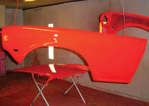
As you can see from the photos, Bowtie6 was treated to an unusual shade of red. It’s used on Dodge Vipers and is extremely bright when seen in sunshine.
Some of the details: All panels were prepared with DuPont epoxy primer, DuPont Sanding Primer and sealer. The outside surfaces were painted with DuPont Chroma Base followed with DuPont Clear Coat. All inside surfaces and underneath the car were done with DuPont Single Stage Urethane and all the painting was done with HVLP guns.
As stated earlier, the car was totally disassembled and each piece was meticulously sanded and prepared to ensure a very straight finish.
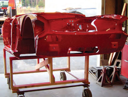
The body shell was mounted atop a special wooden frame (Photo 18) and this, along with the Triumph’s body panels, was sprayed in a paint booth (Photo 19). After all the components dried, the body was assembled and wet sanded with 1200-, 1500- and 2000- grit sandpaper. A high-speed polisher and orbital polishers were used along with 3M polishing compound, swirl remover, and glazing compound to give the car its final shine.
On sunny days with a good wax job, this paint glows and I am extremely pleased with the results. (For more on working with polishing compounds and swirl removal, see page 9.)
To further protect vulnerable areas such as the lower rockers, I purchased some 3M clear tape.
This material comes in different widths and can be cut to perfection. To apply it one only needs a soapy water mixture and some denatured alcohol to activate the tape’s adhesive.I did quite a bit of research on this tape before buying it. At first I thought it might be just a gimmick, but I have noticed that Porsches and BMWs often have this clear tape in certain damage-prone areas. I did not want to leave the rockers or the front nose of the car exposed (especially since it took me forever and a day to get them perfect) so I bought some of this film from a place called Sticker City: http://www.stickercity.com/cutto-fit-sheets/.
Well, after three years of use, the film has stayed in place and has protected the rockers as well as other parts of the car that are exposed to road debris. Another thing to note: It has NOT turned yellow and has not peeled up. I am extremely pleased with it.
Next time we’ll work on the interior and add some finishing touches. Also, we had the wrong area code for Jim Thompson in the last issue. The number should be .
Resources
Good Parts
4361 New Holland Road
Mohnton, PA 19540
Triumph TR6 performance parts
PULLMAX, Inc.
2255 Lois Drive Unit#1
Rolling Meadows, IL 60008
Wilwood High-Performance Disc Brakes
4700 Calle Bolero
Camarillo, CA 93012


