
Building ”Bowtie6,” Pt. 1
He Wanted More Performance From His 1972 Triumph TR6. So, He Used a Chevy V-6 as He Rebuilt His Sports Car.
MY FIRST TRIUMPH was a 1978 Spitfire that I owned for two years. After driving it, though, I was a little disappointed with the underpowered engine and the four-speed, non overdrive gearbox. In addition, it was rather small. So the Spitfire was sold and I proceeded to search for what I would consider a suitable Triumph alternative.
It took several years of looking at quite a few TR6s to find one that was solid and had no rust.
Then, upon purchasing my TR6, I decided to break a few rules: I wanted a classic car with high-performance features and modern components that would not only handle well but also be very fast…while still paying due respect to its British heritage. This was the genesis of a project that would take three years to complete and culminate in the creation of what I’ve called “Bowtie6.”
After three years of driving the car and logging over 8200 miles, it has turned out to be a very reliable and delightful vehicle. The Chevrolet 60-degree 3.4-liter SFI V-6 engine that I placed in this British sports car has excellent throttle response and power and, with the five-speed gearbox I installed, it delivers more than adequate performance on the street as well as when cruising at highway speeds. This car is capable of 90+ mph for sustained stints and still delivers 26-27 mpg. In addition to this, it has been on a dyno twice and the results have been quite impressive.
Yes, my car is far from original but I think it shows what can be achieved with modern components in bringing a 1972 TR6 into the 21st century. So this TR6 is not even your average “conversion.”Instead, I think of it as a modern restoration. And this series will give you an idea of the level of work, creativity and detail that went into building it.
In Storage for Two Decades
After looking at many disappointing TR6 candidates, a friend of mine mentioned he knew of a TR6 built in November of 1971 (according to the commission plate) that was in very good condition. I did not get too excited, but when I saw the car I was pleasantly surprised!
As it turned out, this TR6 (Commission Number CC77169) had been owned by the same family since 1974. The car originally was sold in Clearwater, Florida (not far from Tampa), at Checkpoint Triumph. Its first owner kept the car until sometime in 1974.
This is when the second owner purchased the car and drove it until 1980/81, logging some 86,000 miles on the odometer. Then his son-in-law acquired the car. The son-in-law drove the car for about a year and then parked it for a 21- year slumber in a covered garage.
The car still had its original Pimento Red paint, albeit worn down to the primer in many places, when I acquired it. A deal was struck and the car was purchased for $4000. It even came with a huge envelope with receipts dating all the way back to 1974. This proved invaluable in finding the provenance of the car as well as the previous owners (more on that later).
The Good News/Bad News Report
I bought the car for several reasons: The body was in excellent shape with very little rust from being in a covered garage for 21 years (something hard to find these days).
In addition, the car had spent its life in the South, where no salt is used on roads during winter months. There was no apparent damage anywhere on the body (Photo 1) except for some small dings on the passenger side front fender. After inspecting the frame, it too appeared to be straight and undamaged.
Mechanically, though, the car had several issues that were to be expected from a machine that had been laying dormant for so long:
• The brake system and fuel system would require a full overhaul.
• The engine had not been started, even though there was documentation of an overhaul done sometime in 1980.
• The fuel tank had not been drained at the time the car was parked, causing the fuel to turn into a tar-like substance over the years. Moisture caused the tank to rust severely, thus making it beyond repair.
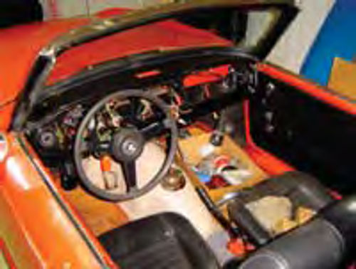
• The interior was in poor shape with tattered seats, non-existent carpet and a delaminated dash (Photo 2).
Disassembly
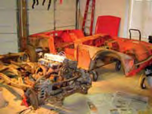
The TR6 was put on jack stands and disassembly promptly begun. After a few weekends, the entire car was apart. No real bad surprises were found on the body shell, except maybe for some minor rust on the floorboards. The frame, however, needed some attention (Photo 3).
Next would be removal of the engine, suspension and exhaust from the frame. It took quite some time to get the frame clean from 30 year’s worth of grease and grime. I used a pressure washer, some Purple Cleaner from the Radiator Specialty Co. (gunk.com/prod_photo.asp). This stuff is really good to remove grease. I also used plenty of Scotch Brite scouring pads and several hard bristle brushes to get into the nooks and crannies. This was all done over a period of several days until I got the frame clean enough to spray paint it. The spray paint used was Chassis Black (from Eastwood) and some Rust-oleum for areas that needed some touch up.
Once the frame was clean, the main problem was obvious: the differential mounting pins were in poor shape. This is a common problem with TR6s and this one was no exception. In addition, the top beam across the frame that actually holds the differential had some hairline cracks near the rear spring perches. This became a concern.
The interior of the car was in poor shape. The seats would need a full rebuild and the carpet would need to be replaced. In addition, the dash had delaminated very badly. The wiring harness was also in poor shape, with several very brittle sections. So, every part was catalogued, labeled and stored in bins for later.
A Major Engine Decision
After getting the car home and prior to disassembly, the engine had been run briefly. It ran fairly well, as expected, but I had some concern as to the type of overhaul that had been done back in the early ’80s. Another concern was what type of components had been used and their longevity. Taking the engine apart again would prove to be costly, so a decision was made to seek an alternate engine. Furthermore, the TR6’s inline six does not have cam bearings nor hardened valve seats. Having all of that done would prove to be costly.
Therefore, an alternative had to be found…
The powerplant of choice was a Chevrolet 3.4 Liter Sequential Fuel Injected (SFI) 60-degree V-6, and hence the car’s new name of “Bowtie6.” The engine was purchased with a matching 5-speed Borg Warner gearbox, wiring harness and Powertrain Control Module (PCM). This engine was the V-6 base option used on the 1994 and early 1995 GM F-bodies (Camaro/Firebird) and is good for 160 hp and 200 ft.-lb. of torque in stock form.
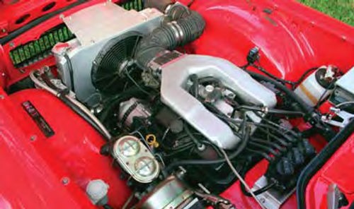
This powerplant was chosen because of my familiarity with GM engines and electronics. In addition, I felt fuel injection was the only way to go and this engine has excellent fuel delivery and ignition systems. An added bonus: the 60-degree V-6 was narrow enough to fit the engine bay without having to cut anything (Photo 4).
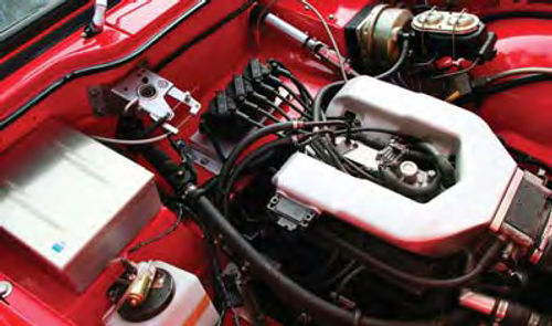
The wiring harness originally designed for the F-body (Camaro/Firebird) was a bit long for the TR6 engine bay but with the aid of the Factory Service Manuals, the harness was taken apart and checked for continuity. Special alterations were made to simplify the harness and it was cut to fit the TR6 engine bay. This ensured a very nice fit, without having extra wires all over the place. In addition, the PCM was mounted inside a special aluminum enclosure as shown in Photo 5.
Relocations Under the Hood
The engine came with an air conditioning compressor and power steering pump. These were removed and by doing so, the engine performs a little better since these two components tend to steal power. However, a special bracket had to be hand-made to properly mount the alternator as well as the idler pulley. This eventually required a special-length serpentine belt.
This engine does not have a distributor. Rather, the PCM controls 3 coil packs with each firing two cylinders.
The coil packs were mounted on a small bracket and this was bolted to the area where the battery usually is located on a stock TR6. In turn, the battery was relocated to a custom enclosure in the trunk. Custom cut and made-to-fit spark plug wires were made and platinum tipped spark plugs deliver the necessary spark to each cylinder.
All six factory injectors were replaced with larger, Accel injectors. Since this required a more precise fuel pressure, a billet adjustable fuel pressure regulator was fitted. This was all dialed in on a dyno for optimum fuel pressure, which is around 41 lbs.
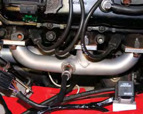
The factory exhaust manifolds are cast iron. They proved to be a problem because their shape did not blend very well with the engine compartment of the TR6. To solve this problem, a set of custom-made headers were fitted. They were made of stainless steel, cut to shape and TIG welded. A special bung was welded in place on each header so the oxygen sensors could be properly mounted. Finally, the headers were ceramic coated so heat would be contained; this also gives the headers a very appealing silver finish (Photo 6).
Incidentally, these headers were made from scrap stainless grab-bars commonly used by people who need a little extra support while moving around in the bathroom. We were able to get several sections and they were all custom cut. They should last a lifetime.
Finally, the header bolts proved to be quite a headache. After several heat cycles they would tend to loosen and cause leaks. After quite some research, I found these trick locking fasteners (made by Stage8) used for this very purpose. They have a grooved head with a special tab that is held in place by a lock ring. The tab is oriented in such a way that when the bolt backs out a tad, the tab touches the exhaust tube and this prevents any further movement. According to the manufacturer, these type fasteners are used by NASA on the Space Shuttle.
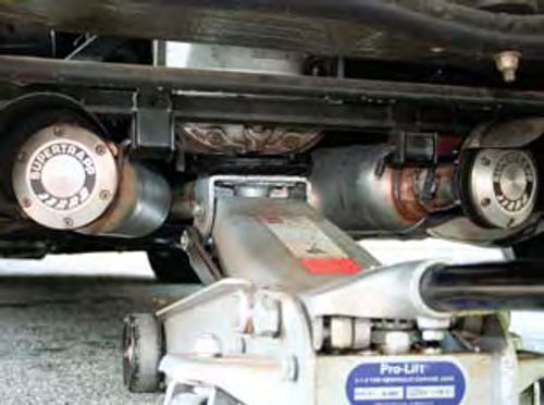
Two down pipes were made and bent to connect the headers to two glasspack mufflers mounted under the car. The downpipes were also ceramic coated. Again, the coating helps contain heat. The glasspacks turned out to be a little too loud for everyday driving, so a SuperTrapp 4” diffuser was added to the end of each glasspack (Photo 7).
SuperTrapp diffusers are used in racing applications and are tuned by removing or adding discs. That is, SuperTrapp’s exhaust outlet is formed by a precise gap between a series of individual discs. Adding discs increases the size of the exhaust outlet, so the more discs used, the louder the exhaust, with less back pressure, which yields higher top-end horsepower. The fewer the discs, the quieter the exhaust, with greater back pressure and greater low-end torque. A happy medium was achieved on a dyno and the exhaust note is aggressive but very tolerable in everyday driving.
Providing Some Breathing Room
With the headers in place, the intake was found to be somewhat restrictive. The single, stock 50mm throttle body butterfly did not give the engine enough breathing room. To solve this problem, the intake was cut on a milling machine. A new upper intake was fabricated and welded in place. Then the throttle body from the Chevrolet LT1 5.7-liter V-8 (as fitted to Corvettes and optional on F-bodies) was adapted. The new throttle body has twin 48mm butterflies and this enhancement has given a much better throttle response.
A set of roller rockers has been installed. The original 1.5 to 1 ratio rockers were stamped steel. These have been replaced with 1.6 to 1 roller rockers. With the ratio change and the new intake, the engine now breathes even better and allows for a higher redline. The valvetrain has also been modified with a high lift COMP cam. The cam was designed to improve the 1000-5000 rpm range. Along with this, a new timing chain, timing gears, lifters and hardened pushrods were added. To further enhance the package, a set of aluminum valve covers, as fitted to Fiero GT V6s, were sourced and adapted to fit. Now, the engine compartment looks as good as it performs.
The larger injectors and valvetrain enhancements have paid off nicely. According to the results of “before” and “after” dyno runs, the breathing capabilities have been enhanced. Power is now being delivered much earlier and holds steady until redline.
Finally, according to the O2 readings, the engine is not running as rich as before and this is producing more power. The final results have yielded 151 hp and 175 ft.-lbs. at the rear wheels. Not bad numbers at all.
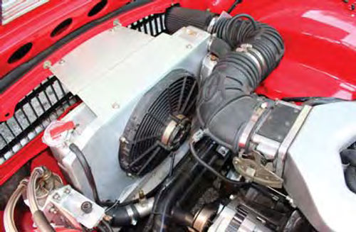
To properly cool the engine, a new aluminum radiator was purchased from a manufacturer that supplies radiators to NASCAR stock cars (Griffin Thermal Products in Piedmont, South Carolina; griffinrad.com).
This radiator provides exceptional cooling due to the large surface area and the heat dissipation properties of aluminum. It is important to note that a special shroud was made to fit the back of the radiator and a SPAL electric fan was fitted (the same brand used by those red Italian cars with the prancing horse on the hood). This fan is a “puller” type as opposed to the less-efficient “pusher” type.
Special attention needs to be paid to the shroud—it is the heart of the system. Without it, hot air is re-circulated around the radiator, not through it. This is a huge misconception among folks: the shroud ensures the air flow is forced through the radiator and thus provides the maximum cooling efficiency. Just mounting an electric fan with those plastic “through the radiator” tabs is NOT the way to properly cool an engine.
A special metal adapter was machined to fit on the lower coolant hose. This adaptor holds a threaded sensor that is attached to an adjustable regulator (via a capillary tube) that controls when the fan turns on/off.
Finally, a special aluminum canister was made and fitted to the side of the radiator to serve as an expansion tank. A sealed General Motors relay is used to handle the power requirements to the fan.
The engine is cooled with a mix of 50/50 distilled water and anti-freeze. In addition, a bottle of Red Line Water Wetter was added for good measure. Even in the heat of summer (90+ degrees) this engine has never run hot. On the contrary, the fan runs and cycles as required for short bursts in stop-and-go traffic. At speed, the fan does not even kick in.
The decision was also made to move the oil filter away from the block and mount it on a remote filter adaptor (Photo 8). This is plumbed back to the engine via Teflon-lined braided steel lines. By doing this, some extra heat can be scrubbed off the oil filter. Finally, the V-6 is filled with Mobil 1 synthetic oil and K&N oil filters are used exclusively because of their ability to trap very small micron-size particles.
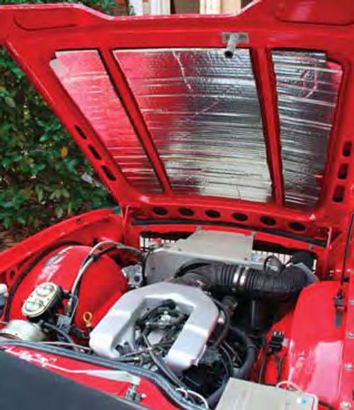
In order to protect the paint on the bonnet (hood) from heat, a special heat shield has been added to the inside of the hood (Photo 9). This material is a combination of self-adhesive foam with a thermal reflective foil and it was cut to fit the inside of the Triumph’s hood.
Frame & Suspension
Upon closer inspection, the frame had some small issues. Overall it was very straight but as noted earlier, the differential mounting area was in need of attention. One of the differential pins had worked loose and the other three did not look much better. Since major repairs would be needed, the decision was made to use a different differential; one that would cope better with the power and torque from the V-6.
The differential chosen came from a Nissan 280ZX. This is the “longnose” R200 unit with a 3.90:1 ratio.
Since the shape is quite different from the stock unit, a new way to mount the differential had to be designed. To accomplish this, the differential mounting beam was cut out and a new carrier made to support the R200 differential. This new carrier also was designed so a set of true coilover shocks could be mounted. The coilover shocks were selected for several reasons:
• Handling is greatly improved.
• They allow for six different damping modes by the turn of an adjuster screw.
• The coilover shocks can be easily serviced: this means springs with different rates can be changed very quickly.
The coilovers attach to the frame on special adjustable perches. These adjusters came in very handy when adjusting the proper ride height. In addition, the coilovers themselves are used to fine-tune the final ride height.
Next, we’ll continue with the suspension work and turn to the brakes.
Editor’s note: While Joe did much of the work himself on Bowtie6, he wanted to acknowledge the invaluable assistance he received from his cousin, machinist Jim Thompson.
“Without Jim’s help, my car would never have become a reality,” Joe said. “Jim is an owner of Thompson Tool in Greenville, South Carolina. He specializes in metal work, making hard-to replace or non-existent body panels, building custom cars, performing engine swaps and doing machine work in general.” Jim’s phone is .


