Test & Rebuild an Alternator, Pt. 2
This Month We’ll Replace the Front Bearing and the Brushes. We’ll Also Run More Tests & Reassemble the Unit.
Editor’s note: Last month, after the alternator light kept flickering, retired auto tech John Armstrong pulled his Delcotron 12-SI and tested several components including the three major “hard parts,” the rotor, the stator winding and the rectifier bridge. He’ll pick up the project at that point. There were 13 photos with last month’s article, so we’ll start here with Photo 14.
IF ALL OF the “hard parts” have passed their tests, you are good to go. If, however, one or more components fail, then you must make the decision whether to rebuild or not.
Seldom do these parts seem to fail but if that is the case, you can avoid the expense of new components by taking parts from another “donor” alternator.
Should a rotor or stator winding be needed, make sure they come from the same amp-rated alternator or you will not have the same output.
Replacing the Front Bearing
If you are going to replace the front bearing, hopefully you have been putting penetrating oil on the rotor shaft so it could soak in and aid in its removal from the bearing. There is a chance it may be easily removed, but that’s unlikely.
To remove the shaft, thread the nut on flush with the end of the shaft threads and using a lead, copper or other soft faced malleable hammer give it a few strikes to see if it will come loose while you hold the housing with your other hand. The nut serves two functions: one, it protects the threads, and should the rotor come free, it won’t go flying somewhere.
This bearing is a slip fit over the shaft; any resistance in removal is due to rust built-up in a 1/2” area between the shaft and inner-bearing race.
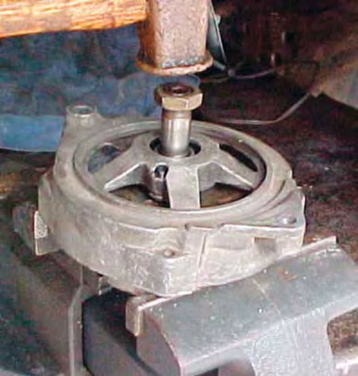
Assuming it did not come out, the next step will be to use a vise (5” minimum) and open the jaws up wide enough so the rotor fits freely in between while either side of the casting is supported by the jaws.
If you don’t have that option then find a section of pipe large enough to support the perimeter edge of the casting with enough room for the rotor to drop down once it is free. PVC pipe will work fine for this. Once again tap the end of the shaft with your hammer (Photo #14).
The pipe or vise offers resistance this time but use caution; too much force could crack the casting. Common sense comes into play here, use a medium-size hammer at best, not a four-pound sledge, and start with light taps and progress to firmer strikes if required. Be patient, this will most always work.
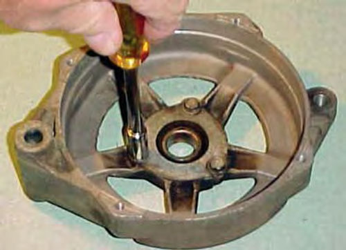
In extreme cases if it will not come loose, use a small thin ignition wrench (5/16” in my application); you know the ones Sears sells in a packet, either metric or standard. Reach between the casting arms and loosen the three retaining bolts that secure the bearing retainer (Photo #15). If you don’t mind modifying the wrench, heat it and increase the offset. It will work either way, but more easily if you bend it a little. The bolts will not have enough room to be fully removed at this point, but don’t worry about that now. Again tap on the shaft of the rotor. Now the rotor will drop slightly along with the bearing that is stuck to it. Repeat the step loosening the bolts some more (miniature needle nose pliers with angled tips can be used at this point to turn the bolt heads if needed). This time you should be able to remove the three bolts completely. Give it a tap or two and be prepared to catch the rotor because you are removing the rotor with the bearing still attached, and the nut will fit right through the hole in the casting.
Pull the Bearing
Once the rotor is out, the bearing can easily be removed from the shaft with a two-jaw puller. I have had to resort to this method, and it will work. If you had a three-jaw puller with small arms, it could possibly fit in between the casting openings where it could support the bearing while pressing against the shaft. This is another possible option. I would advise against using a press. Due to the inability to support the bearing area, there would be a great risk of damaging the casting.
If the rotor was removed without having to unbolt the bearing retainer, then that is your next step. Photo #16 shows the three retaining bolts and plate being removed. This plate is bowed slightly in one direction to accommodate the bearing. To avoid any confusion, mark the outward facing surface.
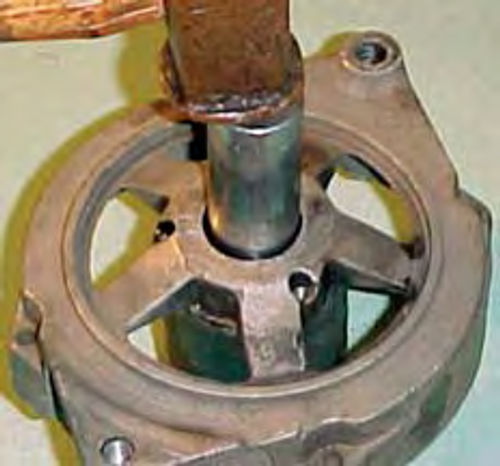
To remove the bearing I used a short section of 2” ID exhaust pipe for support underneath, and a deep socket up against the face of the bearing. This will come out easily, a tap or two is all that is needed (Photo #17).
Wipe out any dirt and set the new bearing in place. In most cases you can easily square it up and get it started by hand. Use the wooden handle end of the hammer to fully seat it. If it is tight, use a large socket that makes contact against the outer edge of the bearing and tap it in, then replace the retainer and three bolts. The rear bearing is a non-load carrying bearing, and seldom requires any service.
Before replacing the rotor, make sure to clean off any rust on the shaft, then put a light coating of lubricant or anti-seize compound where the surface rides under the bearing. Only a small amount is needed, too much and it will just get slung around.
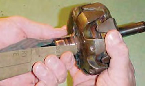
You can either polish up the slip rings now (Photo #18) or wait until you have it mounted back in the front housing if you find that easier. Better yet, if you have a lathe or a drill press with a large enough chuck, secure the rotor by its pulley shaft. Now set it on a slow speed and let it do the spinning while you polish the slip rings using 400-grit or finer abrasive. Otherwise, spin the rotor by hand to polish the slip rings. Wipe or blow off any dust.
Don’t forget to replace the collar that goes onto the rotor before it is fit through the bearing. You will quickly realize if you do because the rotor will drag inside against the casting.
Putting Some Things Back Together

Now replace the collars, fan and pulley in the reverse order from their removal. Tighten as best you can; you can tighten it fully once the alternator’s back on the vehicle.
Set that assembly aside in a safe place, as it won’t be needed until we get to the final assembly.
Testing the Diode Trio
If you don’t have a new diode trio to put in, the old one must be tested. The procedure is basically like the rectifier bridge, but with fewer checks. Begin by connecting the long single leg to battery Negative. Each of the other three connector loops must light the test light. Now reverse the connection, place the test light on the long single leg, and the negative jumper to one loop at a time. The tester must not light.
If any of the checks fail, you must replace the part. You can purchase individual parts for the alternator, or buy a kit like “Victory Lap” from CPI Parts Division. It includes a new front bearing, brushes and springs, the diode trio and the voltage regulator. It is made in the USA and is less costly than buying the individual pieces. They also have a full line of kits for other brands of alternators as well as starters.
Checking the Brushes
Visually inspect the brushes, if they are 1/4” in length or less, they need replacing. In most any instance I would replace them if they are worn at all. After all, you have it open and right in front of you, and brushes by themselves only cost a few dollars. Remove the three screws that retain the brush holder and voltage regulator. Note that two of the screw heads have an insulated washer, while the one closest to the perimeter does not. Don’t worry if they get confused, I will show their proper placement in a later photo upon re-assembly.
Lift out the brush holder and behind that the voltage regulator. Set the regulator aside and take a close look at the brush holder. Spread the metal retaining clips that the brushes are connected to and slide them off. If you see any cracks or damage to the holder, it will need to be replaced. Wipe off the holder and slide on the new brushes.
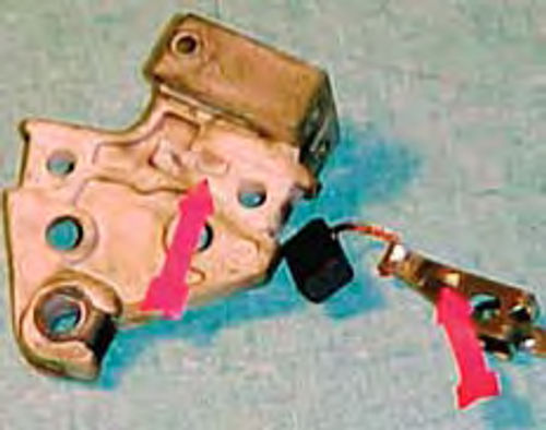
In Photo #19 the red arrows point out the notch in the holder as well as the corresponding depression in the metal clip that lines up with it. Both brushes line up in the same manner.
Slide both the new brushes on until the clips snap into position, now replace the springs in each side of the brush holder and, one at a time, push the brush against the spring seating it into the holder. The holes located on both front edges of the holder are there to retain the brushes during installation.
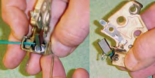
The kit includes a metal pin to slide through these holes, but I feel better using something non-conductive like a toothpick, or even the straw extension from a can of WD-40 or carburetor cleaner, just wipe it clean first. Should you accidentally forget to remove it, there is no harm to the alternator. The left image in Photo #20 shows one brush loaded and secure, while the other is ready to be secured. The right image in Photo #20 simply shows a side view. You can see the brush clip in place with the wire connecting to the back of the carbon brush, and the hole the toothpick will slide through.
Photo #21 shows the holder loaded and ready for installation. I am replacing the voltage regulator with the new one included in the kit. The metal surface goes down against the housing and the two terminals extend out the opening. The brush holder sits directly on top of the regulator, and they fit into each other.
Next line up your three holes with the threads in the housing. Place the new diode trio over the rectifier bridge studs with the long terminal extending over to the closest hole for the brush & regulator assemblies. (See Photo #22.)
My unit has a resistor; some do not— it mounts on top of the diode trio terminal using an insulated screw and across to the hole closest to the two voltage regulator terminals using a non-insulated screw. The last insulated screw goes in the third hole.


In Photo #22 the two red arrows point to the location of the insulated screws. Once all three are installed, they can be tightened (no need to overdo it though). All that remains is to replace the stator winding. First, it’s a good idea to check and make sure the screws that secure the rectifier bridge are tight. The winding can now be set back in place, note your index mark made before disassembly, then tighten the three nuts.
Join the Housings
The final step is to mate the front housing holding the rotor with the rear housing. It’s pretty straightforward, again remember to reference your index marks and, once aligned, slide the two together, drop in the four perimeter bolts and tighten it down.
Snug one bolt, then go across to the opposite bolt and snug it. Repeat this for the remaining two. Once all are snug, you can go back and tighten them.
I have never seen an alternator where the housing bolts were falling out because they were loose, so there is no need to super tighten them. More damage is done by over tightening than you can imagine.
Slide out the toothpick from the rear, and you are ready to install it back on the vehicle. Remember to retighten the nut that secures the pulley and fan assembly. Many people use an air impact tool to remove and replace the pulley. It’s frowned upon, but if you do that, be careful when replacing the nut, you don’t want to over-tighten it.
Make sure there is no question with regards to the condition of the drive belt. If there is, simply replace it, as there is no better time than now.
Resource
CPI Divisions
138 East Main St.
West Concord, MN 55985
“Victory Lap” alternator parts kits