
Test & Rebuild an Alternator, Pt. 1
Sometimes You Don’t Want to Pull and Replace the Old One. Here’s How to Troubleshoot and Fix Your Unit.
WHEN RETURNING HOME the other day I heard a clicking sound coming from my car’s dash. I first suspected it was the trip counter that sometimes has a habit of sticking. It took several days before I realized it was actually the alternator light that was just barely flickering and creating this clicking noise.
The vehicle is equipped with both a factory gauge and a warning (idiot) light. The voltage reading on the gauge was sufficient but a slight pulsing of the needle was noticed.
I knew there was a charging system problem, and thought it may be a defective diode inside the alternator.
Some might simply replace the alternator with a rebuilt unit, but what if you were concerned with maintaining matching numbers or if you had a chrome alternator? You wouldn’t trade it in at NAPA for a factory gray cast aluminum model with who knows what number on it. I prefer to do the repair myself, and it’s not too difficult.
Working With a Delcotron 12-SI
The alternator in question is the popular GM Delcotron with internal voltage regulator. It has been used in many forms including the 10-SI, 12-SI, 15-SI and 27- SI series and probably others, I’m sure. They all have internal voltage regulators and are quite similar in design.
Typically, the higher the series number, the higher the amp output rating. These have been used for many years as original equipment on GM products, and are frequently seen on street rods and many vintage applications whether GM, Ford or others as a “one wire” conversion. The model we will be working on here is the 12-SI and the vehicle is a 1986 Chevy Caprice with a 305 engine. But regardless, the testing and basic removal is virtually the same for most any vehicle.
Some Initial Troubleshooting
If your vehicle has a warning (idiot) light, the only time it should be on is when the ignition switch is turned on and the engine is not running. Not lit? Check for a blown fuse, bad bulb or bulb socket, or a wiring problem between the ignition switch and the alternator.
If your warning light is staying on when the ignition is turned off, try unplugging the side connector from the alternator. Should the light remain on, there is a short between the two leads. If it goes out, you likely have a bad rectifier bridge inside the alternator. You will still need to check it out to be sure. It doesn’t take long, and is easy enough to quickly put back together if you decide an exchange is more practical due to a need for major components.
Finally, with the ignition on and engine running if you experience either a lower than normal voltage reading on the gauge (if equipped) or the warning light is remaining on, you most likely have a charging system problem. This can include something as simple as a worn or slipping drive belt, or a failure in the voltage regulator or alternator. You shouldn’t be able to turn the alternator pulley by hand. You can use the fan behind the pulley for a better grip to try and rotate it. If you can, the belt is too loose and/or worn.
Checking the Maximum Output
The Caprice was showing 14 volts at fast idle. This normally would be perfectly acceptable if not for my flickering warning light at low rpm. Voltage readings will vary depending on battery state of charge, and even the temperature. If your voltage is less that 13.2 volts, or reads the same as your battery did before the vehicle was started, you have a charging system problem. Next you can bypass the voltage regulator by grounding the field winding. This is known as “full fielding” the alternator and will give you the maximum output of the alternator.
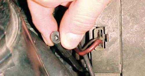
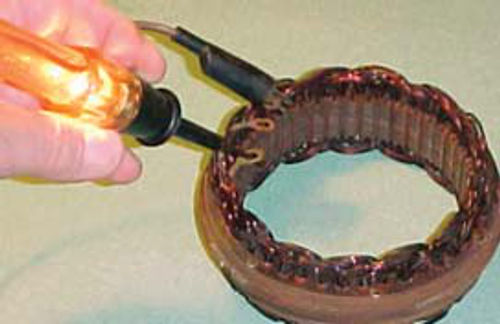
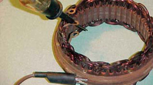
The arrow in Photo 1 points to the small hole in the rear of the alternator that will allow you to reach inside far enough (slightly less than 3/4”) to ground the metal tab on one of the brush clips against the housing.
Photo 2 shows using an Allen wrench to perform this operation. I used a section of small vacuum hose over the end to make it easier to hold, and it affords you protection from the possibility of a low-voltage shock.
Be cautious when performing this test that you don’t accidentally make contact with the battery positive terminal on the rear of the alternator. Usually it will have a protective cap or rubber boot over it, but sometimes it’s missing.
At a fast idle my voltage was just over 18 volts. When performing this test you will audibly know if the alternator is working. You can hear a whining sound distinctly coming from the alternator. If, when performing this test, you show a good voltage reading similar to my 18- volt reading (and you previously had a low or no charge condition), your problem is the voltage regulator. If the test made no difference, you have other internal problems and the regulator may or may not be one of them.
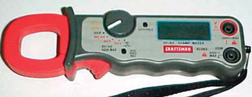
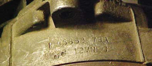
By using an induction type multi-meter like the Craftsman shown in Photo 3 you can easily compare the amperage output with its rating stamped on the case as seen in Photo 4. This may be a little hard to see in the photo but the row of numbers closest to the “ear” is the model number, followed by the amp rating. In this case, 78A. Beneath it is marked 12VNEG, which is rather obvious, 12 volt negative ground. This information may not be visible until after the unit is removed, it depends on its mounting position. The stamping is located behind the ear that is used for the tension adjusting bolt.
Set the multi-meter in the DC amp mode, and clamp it over the battery wire to the alternator. If it is too difficult to attach near the alternator, clamp it over the wire where it’s connected to the battery positive cable. Run the engine @1500-2000 rpm with a full load (headlights on, high fan blower, rear defroster, brake pedal depressed, etc.).
If needed, have an assistant in the car to help. This test can also be performed with the older-type meters that must be hooked up in series. You would disconnect your battery ground first, then disconnect the battery wire on the back of the alternator. The meter connector will be inserted in-between the battery wire and the battery terminal on the back of the alternator. These work fine, but space can often be an issue, and it is more time consuming. Ultimately, your amp reading should be within 10% of the rating stamped on the housing. So on a 78A unit; a minimum of 70 amps would be expected.
If You Need to Pull the Alternator…
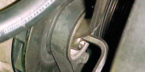
The first step in removing the alternator is to disconnect the battery ground; next it’s a good time to loosen the pulley. This alternator requires a long 15/16” wrench with a deep offset and a 5/16” Allen wrench as shown in photo #5. (If you have no intention of replacing the front bearing, this step is not necessary.) Having the unit still attached to the engine holds it securely. You don’t need to remove the pulley at this time, just loosen it. If you are unable to loosen it, leave it and we will deal with it later once the alternator housing has been opened.
Next, disconnect the battery positive wire from the back, this is usually either a 10mm or 7/16” nut. Now remove the plug from the side of the alternator. This is a simple “squeeze and pull” connection. All that’s left is to remove the swing adjustment bolt and the pivot bolt just opposite it. These usually require a 1/2” and 9/16” wrench (or a close metric variant). Once it’s removed from the vehicle you have the option to take off the lower pivot bolt support. This is little more than a pipe spacer with a bracket welded to it that is secured to the back of the alternator. Removal is not required, but if you are cleaning the housing it makes it easier. If there is an accumulation of dirt or grease built up on the alternator, now is the time to clean it off.
Before you go any further, use a “sharpie” or something similar and make a mark across the alternator where the case splits apart and make sure you mark that gap area in-between the housings. This is the stator winding core frame. This indexing will eliminate any possible confusion during re-assembly of both the housings and also the stator.
A 1/4” ratchet set is handy at this point. Using a 5/16” socket with a short extension, remove the four bolts that hold the front and rear case together. Next separate the two sections. This may require a few taps to free the front section from the stator winding. As you separate the sections you may hear some popping sounds. What you are hearing are the brushes popping out of their holder as the slip rings of the rotor move out from beneath them.
Now you are looking at two sections, the front, which retains the rotor for the moment, and the rear, which has the stator winding around the perimeter, and most of the functioning components. For protection wrap the slip rings at the end of the rotor with several layers of masking tape. You don’t want to risk damaging them. Also put tape over the bearing in the rear housing to keep dirt from falling into it.
Pulling the Pulley
If you are planning to replace your front bearing, now is as good a time as any to remove the front pulley, spacers and fan. I should warn you that this will likely be the most challenging of your tasks as the rotor shaft typically gets rusted to the inner bearing race.
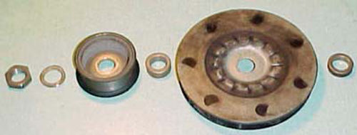
If the pulley-retaining nut was loosened before removal from the vehicle, you can thread it off the rest of the way, but if it was stubborn, try this approach: Use a bench vise and open the jaws wide enough to secure the rotor, holding it by the iron poles, and tighten only enough to keep it from turning. You can now use a socket and ratchet and remove the pulley nut. This method may also be used during re-assembly allowing you to torque the pulley nut 40-60 foot-pounds. (This is actually listed in a Delco Remy service bulletin #1G-266, from Dec. 1, 1978.) Photo 6 shows the pieces removed and laid out in order. From left to right—the retaining nut, locking washer, pulley, collar from in-between the pulley and the fan, the fan itself, and the collar that fits behind the fan and rides against the front bearing. If you feel more comfortable, mark the forward facing side of both the pulley and fan. The collars usually differ in thickness. Should they get confused, remember the one that fits in-between the pulley and fan is there to support the pulley so that it does not collapse when tightened. In other words it should fill the space in-between the two pieces.
Before going any further, put some penetrating oil like WD-40 on the rotor shaft where you see the bearing riding. Repeat this as often as you think of it, and when possible let it sit with the rotor shaft pointing up so it will soak in better. This is to loosen up the anticipated rusted connection between the bearing and rotor. Should your rotor happen to simply slide out, wow, aren’t you lucky!
Prepping for Some Tests
The tests we will be performing are for continuity and not for a specific ohm value. You can use an ohmmeter, but they are usually powered by a 9-volt battery. A better choice is to use a simple test light, jumper wire extension, and the 12-volt battery in your vehicle.
If you are using the battery that is in the vehicle the alternator was removed from, you already have the ground cable disconnected from the battery, so there is no need to be concerned with which terminal the test light is hooked to. I generally connect the test light to the positive, and the jumper lead to the negative. The only concern would be if you were using a battery that’s installed (connected up) in another vehicle to make your tests. Should the jumper lead accidentally make contact with a chrome bumper or other ground surface, you might end up doing some unintended “welding.” By making the connections in this manner you wouldn’t have to worry as virtually all applications will be negative ground.
If you are not sure, there are a couple of easy ways to verify that yours is a negative ground. First, if you can follow the negative cable and visually see it bolts to some point on the engine block, it’s negative ground. Another method is to use the test light itself. Have it connected to the positive battery terminal and verify you have a good connection by touching the negative battery terminal with the probe, it should light up. Now touch some unpainted metal on the engine block, or even the rusty exhaust manifold will do if you scratch it back and forth. If the test light comes on, your system is negative ground. The opposite would be true if you did the same test with the test light connected to the negative terminal.
Some Electrical Defect Terms
Open: An incomplete circuit, a break or opening in an electrical circuit.
Short: To provide a shorter electrical path instead of following the prescribed path. This can also be considered an “unwanted copper to copper connection,” such as in the rotor or stator windings.
Ground: The return path of current to the battery. But when referring to electrical defects it can also be an “unwanted copper to iron connection.”
Inspecting & Testing “Hard Parts”
There are three major alternator components that would be considered “hard parts,” and would be costly to replace with new ones. They are the rotor, the stator winding and the rectifier bridge.
Let’s start with the rotor. First give it a visual inspection. Does the winding appear burnt or discolored in any spots? (Don’t be confused by any dirt build-up on the winding.) Does it have a burnt electrical smell to go along with the appearance? If it does, it may likely have a short circuit. There is a specific test procedure for a short in the rotor, but it requires connecting a battery and ammeter in series with the edges of the two slip rings. The reading is then compared with specifications that exist out there somewhere, but I’m not sure where, so I rely on the visual inspection. Failure is not a common problem, but it can happen.
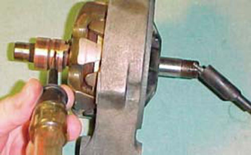
Next, test for a possible ground. Touch the jumper lead to the shaft of the rotor or any of the iron rotor poles that surround the winding (if your jumper lead has a large enough clip, connect it). Now use the test light and touch each slip ring one at a time (Photo 7). You shouldn’t have continuity, so the light should remain off. If the test light comes on, this indicates the winding is grounded.
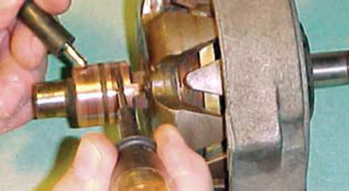
The final test is for an open condition. Touch one slip ring with the jumper wire, and the other with the test light. This time the test light should come on. If it fails to light, the winding is open (Photo 8).
If the rotor fails to pass any of these three tests it will require replacement.
Next we turn to the stator winding. This is what is surrounding the perimeter of the rear alternator housing, and it’s the size of the winding that determines the amp output rating.
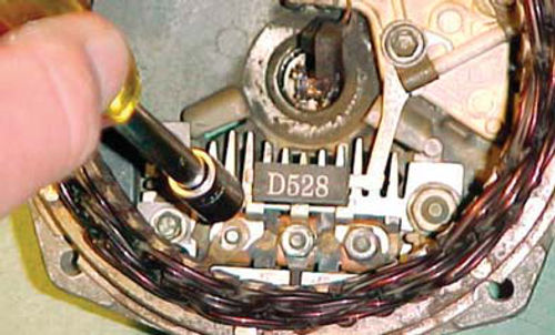
Unbolt the three nuts that secure the stator to the rectifier bridge (Photo 9). A few gentle taps may be necessary once it is unbolted to free it from the rear housing. Do a visual inspection of the winding for any burnt or discolored wires. Once again smell and see if there is a burnt odor to go along with any questionable appearance. This is the only practical test for a short circuit. It’s not unusual to see dirt build-up in areas on the winding, and that’s allowable as long as it’s not heavy. If you have a thick area of dirt, use something like a toothbrush with nylon bristles and brush it off using no solvents or water. Paper is commonly used for insulation in-between the iron core and the copper wire, so it is best to keep it dry. If you have the equipment you can also use compressed air and blow off the dirt, again being cautious around the areas of paper insulation. Look at the three connector leads themselves; are they in good condition, or about to break? There is also a flat crimp type connector that unites the ends if the winding. It is usually located in between the three leads. Make sure it appears to be solid and tight.
The 10-SI alternator has what is called a “Y” type stator winding and can be tested for possible “opens.” The 12-SI and larger units all have a delta winding, and cannot be checked for open circuits. You can check the model number of your alternator against a shop manual to identify it, or simply do the visual check for short circuit and the test for possible ground. I am unaware of any way to tell the difference between the two stator windings through a visual inspection.
While this is a 12-SI stator that normally you wouldn’t test for an open circuit, it looks identical to the one used in the smaller 10-SI, so I will use it for demonstration purposes. Use the test light and jumper extension lead and make contact between any two leads (Photo 10). Again, we are testing for continuity and the light should come on. Repeat this procedure with the other winding lead so that all possible combinations have been made. Should you encounter a condition where the test light does not light, verify its connections to the battery and recheck. Still no light? You have an open in the winding and it will require replacement. Remember this test applies to the 10-SI alternator only. Finally connect the jumper extension to the iron ring surrounding the winding, and make contact, one at a time to each of the leads from the winding, we are checking for a ground (Photo 11). None should light the tester. If the light comes on there is a ground between the winding and iron frame and once again replacement would be required. This test can be performed on both type windings.
The rectifier bridge is the thing with the heat sink “fins” that the stator winding was bolted to. These finned animals are actually two separate pieces that are insulated from each other. The heat sink that is facing the outer perimeter is grounded, while the one opposite it toward the center of the unit is an insulated heat sink. I have already removed the diode trio for these photos. The only thing that was left holding it in was the lower insulated retaining bolt for the brush holder and voltage regulator. Back in photo #9 you can see the diode trio. It is marked D528. You will see its exact placement upon re-assembly.
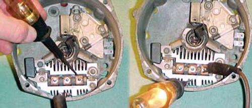
The rectifier bridge testing is simple enough, but there are a total of 12 checks to be made. In the left portion of Photo 12 the jumper lead (which is connected to battery negative) is clipped onto the grounded heat sink, while the probe of the test light is pressed firmly against the flat copper connectors surrounding the threaded stud. There is a copper connector from both the insulated and grounded heat sinks that lay on top of each other with the stud in the center, so pressure is required to assure good contact between the two. Note that most units will likely have these flat copper connectors, but some may not; in that case make contact with the stud for these checks. In this test no light comes on, and the remaining two connections should test the same. Now reverse the connection as shown in the right portion of Photo 12. This time the jumper lead must be pressed down firmly against the copper connectors and the test light is touched against the grounded heat sink. We have light, which tells us there is continuity. Once again the remaining two studs should test the same. So, depending on your polarity hook-up, all should light in one position, and when reversed, none should light.
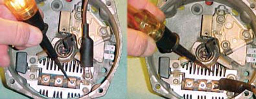
Now we switch to the insulated heat sink. I have clipped the jumper lead to the nut because it was convenient, but it can also be clipped onto any of the fins. See the left portion of Photo 13, and use the test light probe with firm pressure to again make our checks. The light is on, and should be on for the other two remaining contact checks. Again we reverse our polarity as seen in the right portion of Photo 13 and hold the test light against the insulated heat sink, while using the jumper with good pressure against the copper connectors. No light, and the same should hold true for the two remaining connections to be tested.
Next time, we’ll conclude the inspection and rebuild of our alternator.
Resource
CPI Divisions
138 East Main St.West Concord, MN 55985
Phone ; Fax
cpidivisions.com “Victory Lap” alternator parts kits


