
Restoring a 1976 Triumph Spitfire Part 5
Problems With Ill-Fitting Replacement Parts Has Slowed the Project, But Progress Is Still Being Made.
At the conclusion of Installment 4 (March), the Spitfire’s rear suspension pieces had been cleaned, painted and made ready for reinstallation. But before the suspension could be made whole the differential needed an evaluation for possible repair or replacement, and the rear swing axle components had to be reassembled with new bearings, seals and trunnions.
It has been already noted that the differential showed indications of poor repair practices. Aside from the missing gaskets and lock plates and broken Allen screws, the drained gear oil was a muddy brown that suggested water had somehow made its way into the differential despite the Spitfire’s decades of sheltered, dry desert storage. There was some hope, however, in that I could not detect excessive play within the gears.
A cursory examination of the repair manual quickly disabused me of any notions of opening, inspecting and reassembling the differential myself, and so it was delivered to Glen Frost at The MG Shop for inspection and any necessary repairs.
For once, the news was good. Glen informed me that the differential gear set looked good and that the tolerances were within specifications. He simply reassembled the differential with new seals and replaced the broken Allen head screw on the left axle flange.
These Bushings Are Too Big…
Once the Spitfire’s differential was back in my workshop, I attempted to install new rear mount bushings. These mounts are typically rubber bushings inside a metal sleeve and are a “press” fit into the differential housing. The old bushings had simply been drifted out with a few taps of the hammer (March), but I could not install the new bushings without their being damaged. Measuring the new bushings with calipers, which should have been done prior to attempting installation, revealed that they were approximately 0.010 of an inch larger in diameter than the differential mount holes. This was not going to work.
The bushings were returned and a new set of bushings ordered from another vendor. These exhibited the same problem and were also returned. (The vendors each gave me credit for the returned bushings.) Both vendors stated that other customers had not had this problem, which implied that the rear mount holes in my differential case were too small. But on measuring the removed bushings, I found that they were indeed only 0.0015 to 0.002 of an inch larger in diameter than the differential rear mount holes and so fit the application. Spitfire parts catalogs imply that the same rear mount bushings were used throughout the car’s production span of eighteen-plus years, but was that really the case?
I have not yet discovered the source of this problem and probably never will. (Another of life’s mysteries, to which British cars contribute many.)
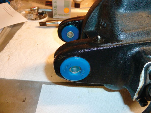
I ultimately obtained a pair of polyurethane rear mount bushings from Rimmer Brothers and was finally able to complete the installation after applying a liberal coating of silicone grease (Photo 1, Rear Differential Bushings).
As noted earlier in this series, I decided to lower the rear suspension of the Spitfire by 1” to improve the car’s handling and appearance. This is accomplished by installing a oneinch lowering block on top of the differential and then mounting the transverse leaf spring on top of the block.
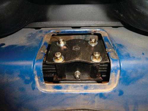
An aluminum lowering block was purchased from SpitBits, and, after some minor file work to adjust the lowering block’s fit to the differential’s irregularities, it was secured in place by the four studs that attach the transverse leaf spring to the differential (Photo 2, Lowering Block).

Longer mounting studs were also sourced from SpitBits to compensate for the additional height of the lowering block (Photo 3, Mounting Studs).

Putting It Back In Place
The differential was now almost ready to install in the Spitfire. There remained only to add fresh gear oil, and the differential was serviced with 18 ounces of Brad Penn GL-4 80W-90. I have been cautioned many times and from many sources to use only GL-4 gear oil for the transmissions and differentials of Triumphs as GL-5 can be detrimental to the “yellow” metals (e.g., brass, copper or bronze) used for various components of older car drive lines. GL-4 gear oil can be difficult to find as most gear oils now sold are GL-5, but it can be ordered from various British parts suppliers. (I ordered mine from The Roadster Factory.)
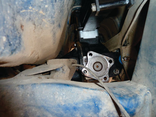
After the differential preparations were completed, the same floor jack initially used to lower the differential from the Spitfire was used to lift it back into place, and the differential was maneuvered onto its mounting points with the help of a friend. A long bolt secures the rear mounting points and two frame studs secure the differential’s forward mounts (Photo 4, Mounted Rear Differential).

New polyurethane bushings from TS Imported Automotive were used for the forward mounts. Once the differential was in place, it was a simple matter to position the rear leaf spring atop the lowering block (Photo 5, Leaf Spring In Place) and secure it with the four studs that pass through the spring box (Photo 6, Leaf Spring Secured).
A “Simple” Solution
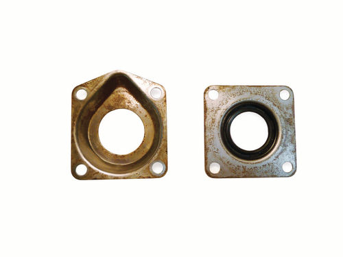
Work also progressed on the rear axles between tasks performed on the differential. The axle bearing housings had already been removed and were cleaned and made ready for new seals and bearings. The bearing housing supports a small needle bearing on the differential side and a roller bearing on the wheel side of the housing (Photo 7, Bearing Housing).
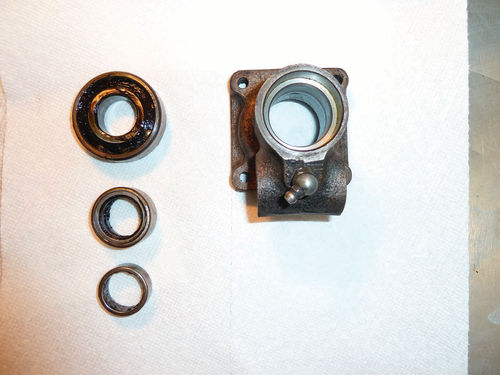
Each bearing has a grease seal (Photo 8, Outer Bearing Housing Grease Seal/ Trap). The bearing housing also contains the trunnion for the attachment of the vertical link as part of the rear suspension. I pressed the needle bearing and its seal into each of the bearing housings (Photo 9, Needle bearing Pressed Into Housing), and then slid the housings onto the axle as far as the flinger cups.
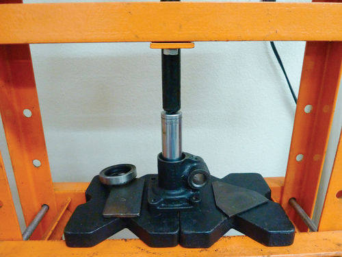
The next task was to press the roller bearings down 3.5 inches of the axle and into the bearing housing itself. I did not have a tool suitable to do this, so, after considering several potential approaches over the period of a couple of weeks, I took the coward’s way out and delivered the axles to The MG Shop to have the work done (Photo 10, Roller Bearings Installed).

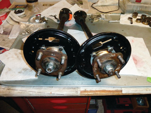
New U-joints were installed at the same time. Glen returned the completed axles in two days and I soon had the new outer grease seals, brake backing plates (cleaned and freshly painted with Rust-Oleum, satin black), grease traps and locking plates secured to the bearing housings (Photo 11, Backing Plates Installed). Installation of the wheel hubs followed, and these were pulled into place by a hub nut tightened to 120 ft.-lbs. (Photo 12, Wheel Hubs Installed). The 36-inch pipe wrench was again used to keep the hub from rotating as the hub nut was tightened.

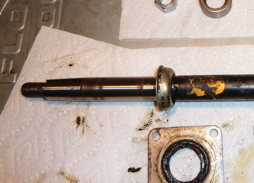
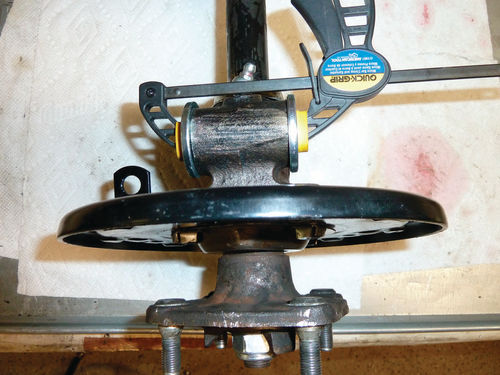
A problem was encountered while installing the hubs. As the hub nut was tightened, the axle was periodically spun as a check, and I started to detect binding on the right axle at 80 ft.-lbs. of torque. This was traced to contact between the flinger and the bearing housing. The Spitfire manual sternly states that the flinger should be positioned 5.75 inches ±0.010 of an inch from the end of the axle prior to the installation of the bearing housings. That is one one-hundredth of an inch, mind you (Photo 13, Flinger). Obviously, I had gotten it wrong and I had visions of disassembling the axle to reposition the flinger. Angst and gloom were finally followed by inspiration! (Inspiration much aided by a conversation with my friend West.) I used a brass punch and light hammer to gently tap the flinger down the axle until there was no further contact with the bearing housing. Some solutions are simple. Don’t over-think it.
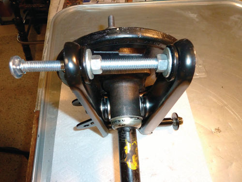
Making a Needed Tool
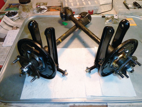
The only item remaining to be done before the rear suspension was ready for reassembly was to install the trunnions in the axle bearing housings and attach the vertical links. This task was somewhat complicated in that the replacement trunnions for the Spitfire application are beefier, i.e., a few thousandths of an inch longer, than the OEM trunnions they replace and so the vertical link arms would not slide into place over the trunnion. This was resolved by making a “poor man’s” spreader that consisted of a five-inch-long 3/8” carriage bolt, two suitable nuts and two washers. The vertical link was positioned on the axle and the spreader used to open the link’s arms enough to slide the vertical link in position over the trunnion (Photo 14, Vertical Link Spreader). A set of clamps was used to hold the trunnion washers in place until the vertical link was positioned (Photo 15, Trunnion Clamps). A bolt through the trunnion secures the axle bearing housing to the vertical links. The process was repeated for the remaining axle/vertical link, and the assemblies were set aside for installation in the Spitfire (Photo 16, Vertical Links Installed).
Should I Bend My Own Brake Lines?
The removal of the rear suspension components for refurbishment created an opportunity to more easily replace the rear brake lines, and I decided to proceed. The major impediment for this was my abysmal line-bending skills. (No, “abysmal” suggests too much talent on my part. “Non-existent” is a truer description.) In any case, my deficient skills served as the perfect rationalization for ordering a set of pre-bent brake lines for the Spitfire from Classic Tube.
Once these arrived I removed the rear brake lines from the Spitfire and placed the new lines alongside for a comparison. The comparison indicated that there would be minimal adjustments necessary to achieve a good fit, and this did prove to be the case (Photo 17, Old and New Brake Lines).

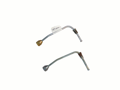
There was, of course, one issue. British Leyland, in their infinite wisdom, decided to transition from imperial to metric fittings on the Spitfire brake lines for the 1976 model year. But instead of changing all the brake lines to metric, they did so only for those lines connected directly to the master brake cylinder. All other brake lines and their three-way connectors are imperial. Someone at Classic Tube did not get the word, however, and the left rear brake line is fitted with a metric connector. Fortunately, the old brake line seems to be in acceptable condition and it will be reused after a thorough cleaning (Photo 18, Left Rear Brake Lines).
A Deadline is Near
I am not as far along as I had hoped to be by this time, particularly since Triumphest 2017 is fast approaching, but progress has been steady. (Triumphest is September 21-24 in Flagstaff, Arizona. Visit www.Triumphest.com.)
Parts fit problems have continued to be a significant issue, but the vendors have been more than willing to work with me to overcome them. (I have come to know some of the vendors quite well over the phone.)
The next phase for the Spitfire will entail the installation of the axle half shafts/vertical links, radius rods and rear shocks to complete the rear suspension rebuild. The rear drum brakes will be installed with new wheel cylinders and the brake lines attached. The fuel tank will be removed and inspected for needed work and/or replacement as will the fuel lines.
There have been big changes on how the Spitfire’s engine work will be accomplished, but that report will be saved for the next installment.
Resources
Rimmer Brothers Ltd. Triumph House, Sleaford Road, Bracebridge Heath, Lincoln LN4 2NA www.rimmerbros.co.uk
The MG Shop 936 E. Gilbert Drive, Tempe, AZ 85218
TS Imported (TSI) Automotive 108 S. Jefferson St., Pandora, OH 45877 www.tsimportedautomotive.com
Spit Bits P.O. Box 281, Lincoln, CA 95648 www.spitbits.com
The Roadster Factory P.O. Box 332,Armagh, PA 15920 (Customer Service) www.the-roadster-factory.com
Classic Tube 80 Rotech Drive, Lancaster, NY 14086 www.classictube.com


