
Restoring a 1976 Triumph Spitfire Part 4
It’s Time to Remove the Rear Suspension and Rebuild Some Components. Some of the Work Was Easy and Some of It, Well…
In the last installment of this series, the Spitfire’s front suspension was completed or, at least, I thought that it was. (More on that later.) This time we’ll begin the Spitfire’s rear suspension rebuild, and the differential will be removed for cleaning and assessment.
When the Spitfire 4 (aka Mk I) was introduced in October of 1962, it came equipped with an independent rear suspension consisting of swing axles and a transverse leaf spring that was bolted to the top of the differential housing. Radius arms were used to maintain rear suspension alignment. This setup, inherited from the contemporary Triumph Herald sedan, was relatively simple and inexpensive, but the roll stiffness of the design also resulted in the handling problem known as the “Spitfire Tuck” or a condition where the rear wheels could “tuck” under the car during hard cornering, resembling the retraction of an aircraft landing gear.
In the early Spitfire Marks, this unfortunate condition could be mitigated by a dealer-installed camber compensator for the rear axle. By the time my Spitfire 1500 arrived some 14 years later, a more satisfactory solution was provided by the factory in the form of longer axle shafts to provide increased negative camber of the rear wheels and the introduction of the “swing-spring” suspension, which modified the transverse spring setup to reduce the roll stiffness that caused the Spitfire’s tail-happy handling.
Many critics have characterized the Spitfire’s rear suspension design, particularly on the early Marks, as “crude” (and it was), but I think of it as groundbreaking for a low-cost sports car of that period. The Jaguar E-Type, for example, which was introduced in 1961 and preceded the Spitfire by only a year, was the first of the Jaguar Sports cars with an independent rear suspension. The C2 Corvette with its independent rear suspension was not introduced until the 1963 model year. The TR4A, the Spitfire’s big brother, did not receive an independent rear suspension until 1965.
The Disassembly Begins
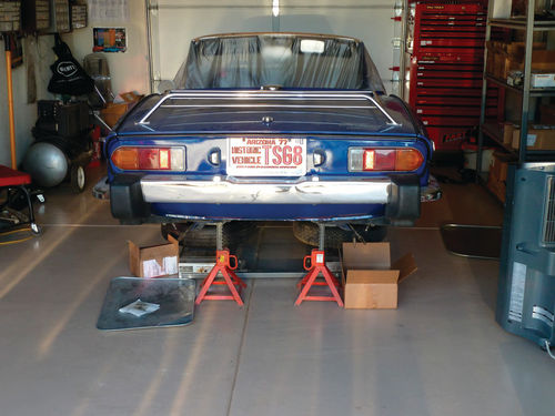
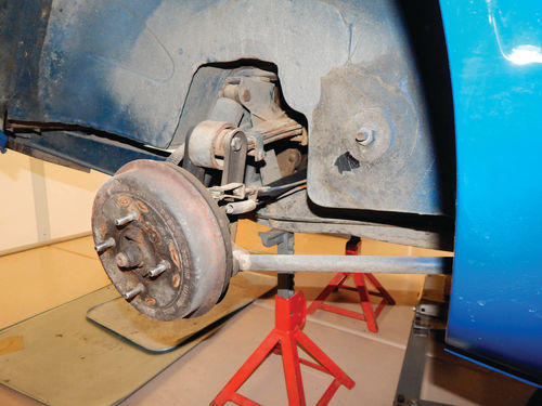
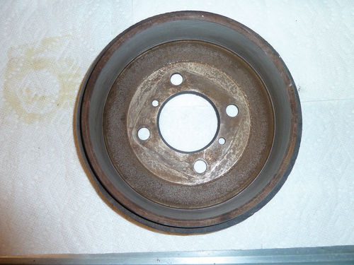
To get started, the rear of the Spit was raised and placed on jack stands and the wheels removed to expose the rear brake drums (Photos 1&2). Both drums were pulled after removing two screws that secure each drum to the drive flange. The drums were subsequently delivered to Bailey’s Brake Service in Mesa, Arizona, to be measured for wear and roundness and for resurfacing. Both drums checked out OK (Photo 3). The brake drums were followed by the removal of the parking brake cables, brake shoes, springs and the rear brake cylinders. The brake shoes still had substantial material remaining, but will be replaced by new shoes from SpitBits as they appeared to suffer from grease contamination.
Disassembly of the Spit’s rear suspension was straightforward and rapid. The rear tubular shocks are held in place by two bolts that connect them to the car’s frame and vertical links respectively and were quickly removed.
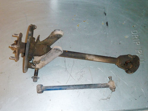
Next in sequence for removal were the axle half shaft assemblies, which are secured to the Spit by vertical links that serve as the attachment point for the axle’s combination bearing housing/ trunnion. The vertical links themselves are secured by two bolts, one of which attaches the top of the link to the leaf spring and a second that attaches the link to a radius rod which is, in turn, bolted to a mounting point on the frame. Prior to removing the vertical links, however, I first disconnected the U-joints that join the swing axles directly to the Spit’s differential. Once this was done, the vertical link bolts were removed and the axle assemblies easily removed as a unit. The radius rods were each also taken out at this time (Photo 4).
Addressing the Leaf Spring and Differential
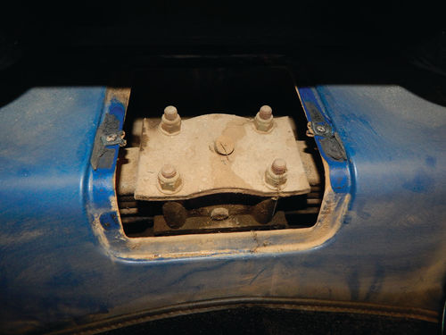
Removal of the Spitfire’s rear leaf spring was next. The leaf spring is attached to the differential via a bracket (known as the spring pivot box) that secures the spring to the top of the differential with four studs. The pivot box is reached by the removal of an access panel in the Spit’s interior (Photo 5). Once the four stud nuts were removed, the leaf spring was lifted from the differential with the help of my daughter, Erica, and placed aside for later work (Photo 6).

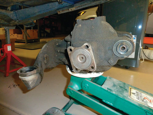
With the suspension components out of the way, the three bolts securing the Spitfire’s differential to the frame were removed and, again with Erica’s help, it was lowered from the car using a floor jack and set aside (Photo 7).
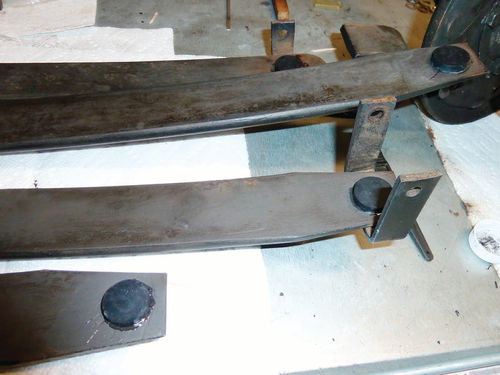
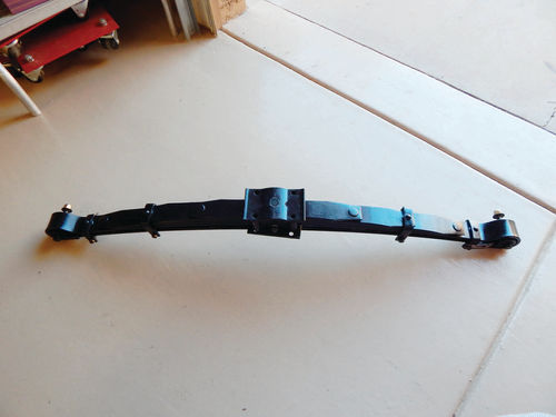
As the suspension components were now removed from the Spit, I decided to work first on refreshing the leaf spring. The spring was disassembled while taking careful note of the original orientation of the individual leaves for reassembly as cautioned in the manual. Inspection of the individual leaves revealed no cracks or breaks, and so they required only a wire brushing to remove 20+ years of dirt and rust prior to a quick coat of Rust-Oleum satin black (Photo 8).
Once the paint was dry, I reassembled the spring while making sure to apply a thin coat of graphite grease to the top of each leaf. I installed fresh rubber spring thrust buttons between each leaf, these being held in place by five-minute epoxy for ease of assembly (Photo 9), and a new pivot box spring pad that is located between the top leaf and the pivot box. The old spring end bushings had been pressed out and new ones installed while the leaves were still apart. The spring leaves were compressed with a vise to aid the installation of the spring pivot box, and, once again, Erica was quite helpful in this process (Photo 10).
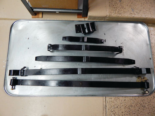
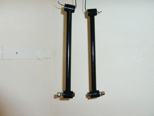
A couple of quick and easy jobs followed. (Yes, there are some in vehicle restoration!) I used a bench-mounted wire brush to clean the radius rods and they were then painted with Eastwood’s Chassis Black paint. New bushings from TS Imported Automotive were installed at each end (Photo 11). And, of course, the easiest job was when I decided to drop off the vertical links at Pro-Strip in Mesa to be sand blasted and powder coated satin black (Photo 12).

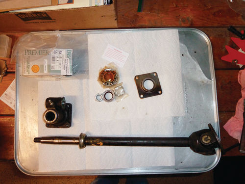
Next Came the Axles and…
Of course, the Gods of Car Restoration, being the contrary creatures that they are, decree that an easy job must be compensated by a difficult (impossible?) one. In this case it was the disassembly of the Spitfire’s axles. The Spitfire swing axle is a half shaft with a U-joint that attaches to the differential at one end and a combination axle bearing housing/ trunnion secured to the vertical link at the other. Just to the outboard side of the bearing housing is the wheel hub, which is pressed onto the tapered portion of the axle and secured by a large nut. This arrangement is somewhat similar to that encountered when working on the axle of my ’58 Triumph TR3A (see the August 2015 issue of Auto Restorer) and, indeed, I had a hub removal tool especially made for the TR3A. I was also in need of a hub removal tool for the Spitfire as the wheel hub has to be removed to access the axle bearing housing. Can I use the TR3A hub removal tool for the Spitfire? Of course not as the lug patterns are different.

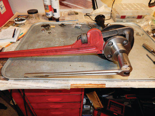
An appeal to the Triumph club to find if anyone already had the tool did not have positive results, so I ordered a hub removal tool from Canley Classics in the UK (Photo 13). Once the tool arrived from Canley, I set about the hub removal task. The left axle wheel hub removal was actually quite easy. The removal tool is attached to the hub using the four existing wheel hub studs, and it has a large center bolt that is used to apply pressure on the axle shaft to separate it from the hub. A very large and inexpensive pipe wrench, purchased from Harbor Freight specifically for this purpose, was used to anchor the hub to prevent it from rotating as the large center bolt of the tool is tightened with a breaker bar to pop the hub free (Photo 14). This technique worked very well with the left axle as the hub came free with a very definite pop while applying only a moderate amount of torque.
The right axle was quite another story. I applied torque, heat, shock with a hammer, copious amounts of Kroil, and even applied pressure directly to the axle with a 12-ton press until the press frame began to distort. (Admittedly, it is a cheap press.) I used the techniques singly and in combination. But the right hub would not separate. I worked on this axle for two weeks to no avail. I even considered buying a new axle assembly, but was put off by the near- $400 price tag.
Force to the Rescue
Deliverance came during a visit with my friends, West and Roy, who had helped me so much during the restoration of the TR3A. On a whim, I decided to bring the recalcitrant axle with me to California. Once there, we attached the hub puller and tightened the center bolt, put the axle assembly in West’s 20-ton press so that additional pressure was exerted against the center bolt of the hub puller, applied heat to the hub, and used a hammer to shock the assembly by tapping down on the U-joint collar.
Finally, with a mild “plop,” the hub came free, and I have come to a new appreciation for the application of pure brute force. On returning to Mesa, I used my 12-ton press to remove the axle bearing housing/trunnion in preparation for replacing the axle bearings and seals (Photo 15).
More Thought Is Needed Regarding the Differential
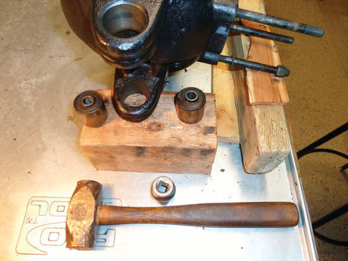
In between the fruitless assaults on the right axle half shaft, I turned my attentions to the differential. Hours were spent cleaning the case of bakedon oil. The original rear mounting bushings were drifted out with a 1” socket and brass hammer (Photo 16). The drained gear oil was a dirty brown, but at least there appeared to be no metal particles in it.
While working on the differential, I was soon able to develop a theory as to why the left axle hub was so much easier to remove than the right. Work had obviously been done on the left side suspension and it had obviously been disassembled at an earlier period in the Spit’s history. The work had not been done well. The gasket and locking plates for the axle hub bearing grease shield were completely missing, and an Allen screw that, along with three others, holds the flange of the left inner axle shaft to the differential had been broken off in the case (Photo 17). In addition, the coating of bakedon oil covering the differential case indicates that one or more of the seals are shot. So I am at this point still assessing the differential to decide how to proceed; whether to just replace the seals and Allen screw or to go forward with a full rebuild/replacement. I would prefer to keep this differential as the serial number indicates that it is original to the car (Photo 18) and replacement differentials, though still available, are getting difficult to find and therefore expensive.


Plans Have Changed
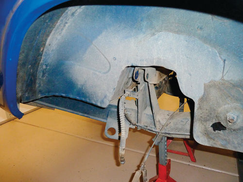
As is usual for restoration projects, the planned work sequence for the Spitfire has changed some. I had originally intended to complete the rear suspension and reinstall it before replacing the brake lines, but these are now so accessible that I will change them before the suspension components are reinstalled (Photo 19). I have also given in to temptation and decided to lower the Spit’s suspension by one inch to improve the car’s handling and appearance. This will require a 1” lowering block in the rear and a set of shorter springs for the front suspension to replace the current springs. (Yes, this will require rework of the front suspension, but it is at least of my own volition.) The requisite parts can be acquired from SpitBits and are already in my stash.
In Part 5, I will continue rebuilding the axle half shafts and, hopefully, come to a decision on the path forward for the differential. Work will also be initiated on replacing the brake lines, which should be interesting as line bending is on the long list of talents that I do not possess!


