
Making Engine Parts at Home
Parts for Uncommon Projects Often Aren’t Readily Available. But You Can Make Many of Them Yourself.
SEVERAL YEARS AGO I had an antique engine that I wanted to restore. Parts were unavailable, but I had recently purchased a 12 x 30-inch lathe and learned to make a few basic cuts. Armed with my newly acquired lathe, I soon found that I could easily reproduce all of the parts that I needed and since then, I have made parts for many engines. The only three engine parts I have not yet made include a crankshaft, camshaft and engine block. Following are a few of the parts that can readily be made in the home shop.
Pistons and bearings are probably the most-needed parts for uncommon engine restoration jobs.
Other parts that are often included on an engine project’s replacement list are valve guides and seats.
Cam Bearings
More often than not, cam bearings are needed to complete a restoration project. If replacements are available, they can be very costly. For example, I recently priced a set of three cam bearings for a friend’s engine at $300. For about $25 and an hour or so of work, I knew that I could make them and have material left over for another project.
Bearing materials are selected by the type of lubrication involved, surface speed, hardness of the shaft or surface and the cost of the bearing material. Hard bearings are not used on soft shafts but camshafts are hardened and do not require soft bearings. Therefore, bronze bearings work well in this situation. SAE 660 bearing bronze is readily available and until just recently was very inexpensive.
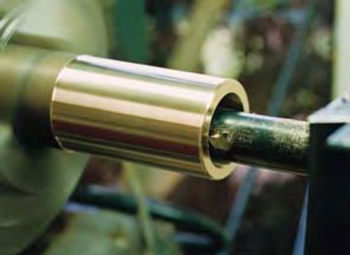
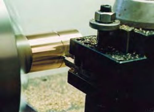
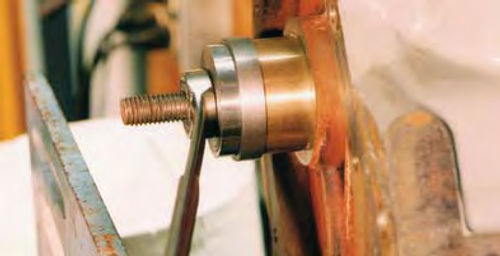
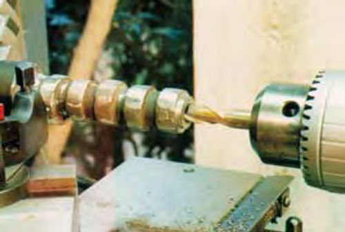
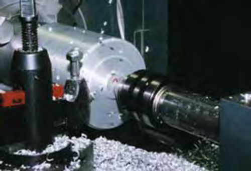
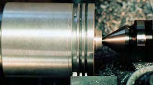
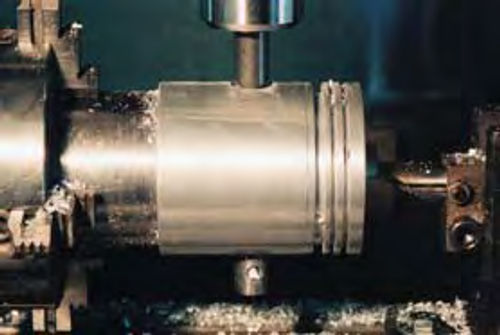
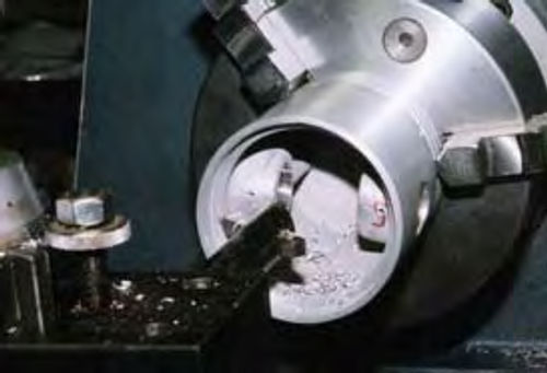
The first thing to do is accurately measure both the shaft journals and bearing bores in the engine block. In the lathe, chuck up a section of bearing bronze and cut the outside diameter. Make the OD (outside diameter) about .003- to .005-inch oversize for a press fit (Photo 1). Bore the ID (inside diameter) about .003 oversize (Photo 2). “Part” or cut the bearing to length (Photo 3).
When you press the bearing into the engine block, the ID should shrink a thousand or so. After installation, the final ID is finished as required with a brake cylinder hone. A really industrious person would measure the shrink and cut the ID accordingly.
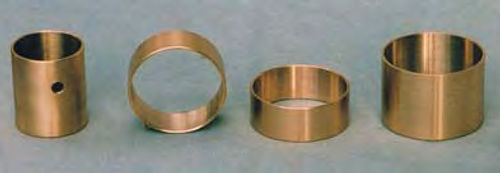
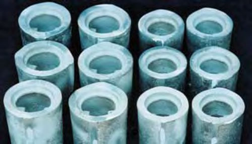
In photo 4 you see a set of homemade bearings ready to be installed.
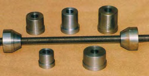
An inexpensive cam bearing tool is made in the shop from a piece of threaded rod and a few short scraps of steel rod (Photo 5). The bearings are pressed into place (Photo 6) and finished as required using the brake hone. The bearing is carefully cleaned to be sure that there is no residual abrasive left from the honing process. It required much less time to make and install these bearings than it took to locate a commercial set.
Some Quick Rod Bushings
Rod bushings also fall into the quick to-make category. In this particular application, the pistons used 59/64ths diameter pins. I am making new pistons and neither wanted to find or make such bushings or pins, so I went to a more standard size of 7/8ths. It took about an hour and a half to make and install the bushings. It would take longer to drive to the parts store and back!
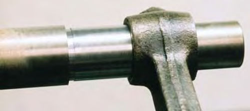
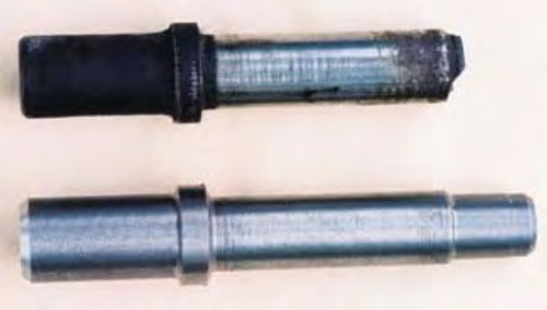
The first order of business is to make a tool used to press out the original bushings and press in the new bushings. I chuck up a section of steel rod and turn steps on it to .010 less that the ID of the new bushing and about .010 less than the OD of the old bushing. This allows me to remove and install the bushings without getting the tool stuck in the rod bore (Photo 7).
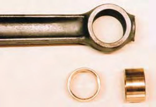
In photo 8 you can see the rod and new bushings. In this case, there are two separate bushings with a gap for oil flow between them.
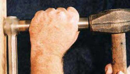
The bushings are installed using the tool made earlier (Photo 9).
From Camshafts To Valve Guides
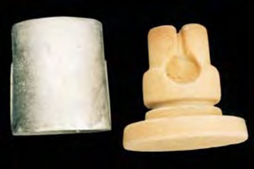
Valve guides may be cut from bronze bushing stock, or from old cast iron camshafts. Camshafts have a hardened surface that should be removed with a hand grinder before machining. Plan on removing about .050 from the surface. Often, you can see a difference in the metal. The harder surface material is whiter while the softer material is a little more gray. Once the hard surface is removed, they usually cut like butter. In photo 10, a section of an old cam is chucked up at a journal so that it runs fairly straight. It is then center drilled and turned to the required diameters. The valve guide is drilled and finished by reaming the bore to size. The old and new valve guides are seen in photo 11.
While it is best to use new hardened valve seats, cast iron seats may be made. I have accumulated several hundred hours’ running time on valve seats made from old camshafts. As you might expect, cast iron seats hold up better on the intake side.
The old valve seats, of course, must be removed from the block and this is easily accomplished by first welding a small bead around the valve seat. While you’re doing this, be careful to not weld the seat to the block. When the weld cools, it draws the seat in, shrinking the OD. The seats may then be pulled out with a finger.
Making seats is similar to making valve guides in that the hard surface must be removed before machining.
The OD is finished .005 larger than the seat cutout in the block. The ID is bored and the seats are parted off as needed. Usually, I can get the seat height within a few thousandths.
If all of the seat heights must be exact, I put them on my Harbor Freight surface grinder to finish them. Using a home made seat cutter and commercial stone, the 45° angle is cut after installation. The valve seat tool has removable pilots to fit various diameter valve guides.
Making Pistons Takes Some Time
Many older engines have been bored oversize more than once, so finding replacement pistons can be difficult. And if they are available, they can cost more than a completed project is worth. Making a set of replacement pistons is one of the first projects I tackled as a young home machinist. While a little time consuming, it is not a particularly difficult task.
First, a set of piston blanks must be cast in the home foundry. I usually melt a pile of Chevy pistons and pour aluminum ingots one day. I make the sand molds and pour piston blanks the next day. The inside shape of the piston is formed by a “core” of sand and molasses that has been baked brick hard in our kitchen oven (Photo 12). Two sets of piston blanks for two different engines are seen in photo 13.
A short mandrel is made from a section of scrap steel rod. This holds the piston blanks in the lathe while turning (Photo 14). Using a micrometer, the final cut is carefully measured at the beginning, in case adjustments are needed. Three ring grooves are cut at once using a homemade tool (Photo 15).
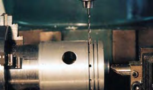
The pinhole is bored and reamed to size as seen in photo 16. Oil holes are drilled (Photo 17) and the pin-retaining ring grooves are cut. Each piston is weighed on a triple beam balance and material is removed from inside the skirt as required to balance the component set (Photo 18).

In order to get the “egg shape,” the pistons are returned to the lathe, which is held in the off position. They are shaped by hand using a file and micrometer. A set of pistons with a spare is seen in photo 19.
TV or Machine Tools?
With a little time invested, a beginner can quickly learn the basic cuts needed to make many engine parts in the home shop. Check with your local community college, it may have a machine shop program to get you started while you are saving for your lathe.
The price of machine tools has come down to the point that almost anyone willing to forego the monthly cable bill can afford them. For very little expense, a small foundry may be set up to make replacement castings.
Learning something new is time well spent. With a little effort, you will impress both yourself and your friends with what you can do!
Editor’s note: Along with writing articles for Auto Restorer, Steve Chastain, a mechanical and materials engineer, has written a variety of how-to books on metal-working subjects such as building a home foundry, metal casting, making pistons, building a home generator and making a sand muller.
For more on Steve’s publications, see: www.stephenchastain.com.


