
Makin’ Them Roadworthy Prep Your Model A for Touring, Pt. 2
Last Time We Started You On Your Way to Carefree Cruising. Now We’ll Help You Steer, See, Stop & Idle.
Editor’s note: As we said in Part 1 of this series, tripsin your Model A are more fun if you’re driving… and not stopping along the way to make repairs. To help keep you on the road and off the roadside, we’ve looked at the starter system, engine condition and the fuel system. This month, our maintenance discussion will include the brakes, steering, wiring, charging system and engine rod knocks. There Were 15 images with last month’s article, so this month we’ll start with Photo16.
Brakes
The mechanical brakes originally supplied on Model A Fords will stop your vehicle provided the adjustments are correct and at specifications.
The most common adjustment problem is when the front brake levers are vertical or “behind” the pivot point, and/or the lever tilt from one side to the other is different.
In the first case, you lose the mechanical advantage on the front brakes. In the second case, the car may pull to the left or right.
If pulling to the left, the “quick answer” fix is to adjust the right front brake shoes a “few clicks” to straighten up the brake action. Right? Wrong!
Take a look at Photo 16 and note the brake angle is tilted forward of the pivot point about 3/8-inch (brake pedal off). This is ideal for applying properly adjusted brakes. The levers will be vertical with the brakes applied and the wheels locked up.
Both left and right levers should be at the same angle for equal pull resulting in equal mechanical advantage.
In summary, pull all the wheels and drums. Inspect the linkage, shoes and drums for operation, worn-out linings, and grooved or out-of-round drums. See Photo 17 to fix a situation where a brake shoe edge is dragging on the drum.
Disconnect the brake rods front and back. Note: In my experience the rear lever angles are always equal and correct.
Install the drums. Adjust the backing plate (square head) adjustment screws inward to lock up the shoes to the drum (rods disconnected). Back off all brake shoes to a light equal drag (usually 6-8 clicks). This establishes the correct shoe to-drum clearance.
Check the cross-shaft arms. They should be vertical with your foot off the pedal.
Re-connect the brake rods. You must adjust the rod clevis yokes to make the rod length fit the brake lever angles.
Then, have a helper apply the brake pedal to create some drag on the drums. The back drums should have slightly more drag than the front drums. Side-to side drag should always be equal, both front and back.
In most cases, before adjustment the rod length will be unequal from 1/4 to 1/2 inch.
Test the drag on all four drums by rotating the drums with a screwdriver locked into the drum studs.
Install the wheels and test the drag again. Side-to-side drag must be equal. As noted, the rear brakes should drag slightly more than the front brakes with around two inches of pedal depression. Make sure all wheels rotate with a slight drag with your foot off the brake. Jamb nut all the clevis yokes and cotter pin the clevis pins.
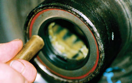
If the rear axle seals were leaking, repair them as outlined in Photo 18.
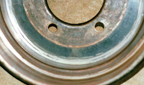
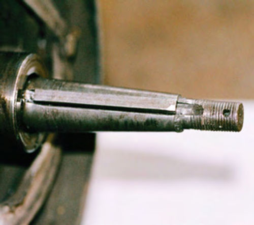
Upon final assembly of the rear brake drums, check the axle key slots and torque the nuts to 80 ft.-lbs. Line up the castellations and install new cotter pins. (See Photo 19.)
Now it’s time for a road test. If it pulls, adjust the brake rod clevis yoke one complete turn (360) at a time on the opposite side of the pull. Do not change the backing plate square head adjustments screws.
Test drive 100 miles. The pedal will “go down” as the lining wears and “seats in.” Adjust the backing plate adjustment screws for equal side-to side drag and slightly more drag in the rear than the front.
Steering
Does your Model A shake violently when going over the railroad tracks at 15 mph? Do you turn the wheel three inches before the front wheels start to turn?
So, adjust the steering gear box. Right? Wrong! First, test the steering free play. If it’s over one inch inspect and “tune-up” the front end.
Inspection: Perform a visual inspection. Have your helper wiggle the steering wheel back and forth, vigorously, for 4-6 inches.
Check the following items: Steering box loose on frame, Pitman arm loose on steering cross-shaft, Drag link front and back joints, loose; Connecting steering tie rod ends, loose; Wishbone ball loose in socket, Wishbone spring perch nuts (Is there rust? It’s loose!), Spring saddle loose, Wheel bearings, mis-adjustment; King pin vertical plane, in and out play; King pin end play, Lift wheels and test for steering binding. Service: lubricate joints and steering box.
Alignment: Check the camber, caster and toe-in. The camber and caster should be equal on both sides.
Measure the toe-in. We have experienced up to one inch toe-in and up to one inch toe-out. Ideally, the toe-in should be 1/16- to 1/8-inch.
Excess toe-out will allow the car to wander, causing continual steering correction at all speeds.
Excess toe-in will cause tire scuffing and excess wear.
Lighting/Wiring
Does your lightswitch rotate when you turn the steering wheel? Are the lights dim?
Grounds: The grounds (or lack of) are usually the cause for dim lights. The ground circuit is through the bulb holder, the headlight mounting bracket, fender brace, frame (rivets and joints), and the battery ground at the frame cross member. In other words, there are opportunities for “lots-a-rust” since 1931, yet all joints must be shiny clean.
The battery redundant ground outlined last month in the Starter System maintenance section will help a bunch. Ideally, each joint should be disassembled, cleaned, oiled and re-assembled.
In the case of rivet joints, you may consider drilling out one rivet, scraping the surfaces, and installing a bolt and nut.
An even better way is to solder a 14- gauge wire at the bulb holder and route it straight to the battery ground point. Install this ground using an eyelet to fit the ground bolt. This technique can and will work on all the lights.
If the lightswitch rod and lever rotates: Light switches, the spring, and horn rod are available from Model A parts suppliers. In my experience, these items should all be replaced if your horn does not work, and/or the lever rotates when turning the steering wheel, or the switch contacts are loose.
When purchasing a horn rod make sure it is “seamless” tubing.
A horn rod with a seam, (not secured) will twist, and the switch will not rotate for proper contact.
One parts source is Bratton’s Antique Auto Parts in Mount Airy, Maryland, (Brattons.com).
Startup
Put twogallons of gas in the tank and check for leaks. Fill the cooling system with water for now. Check the oil level. Adjust the gas needle (choke) valve to one (1) turn open from closed. Turn on the gas lever.
Start Up: Retard the timing (spark lever up). Set hand throttle to 1/4 open. Turn on the key. Push the starter button. During cranking, pull choke rod up and release in one second.
After startup, hold the gas pedal about 1/4 open. Let the engine smooth out.
If the engine starts to die, pull the choke rod slightly to see if the rpm picks up. In this case the mixture is lean. Open the gas adjusting needle 1/4 turn, to see if the engine smoothes out and holds its rpm.
If the engine sounds “blubbery,” adjust the gas needle valve 1/4 turn toward closed (lean). See if the engine smoothes out at 1/4 throttle.
Idle Mixture: Set the spark lever up (retard timing). Adjust gas adjusting needle to 1/2 turn open. Adjust the engine idle speed to 400 rpm. Adjust the idle mixture screw to the rich side (turn counter-clockwise). Then turn the idle mixture toward lean (clockwise). Turn toward lean until the idle rpm starts to drop. Open (counter-clockwise) idle mixture screw 1 turn (360) toward rich to restore the best idle.
Spark Lever: Retard timing (lever up). Advance timing (lever down). Does the idle speed increase? It should. If so, the timing is correct.
On subsequent startups, note if the engine “kicks back” during cranking when the spark lever is up. If this happens, the timing is advanced slightly. If so, loosen the cam lobe screw and retard the timing rotating the cam lobe in the direction of distributor rotation 1/16-inch at the rotor notch. This would be in the counter-clockwise direction. Recheck for engine kickback during cranking.
Power During Rev Up: If the engine seems to lack power during rev up, try adjusting the cam lobe slightly toward the advanced position. Loosen the cam lobe screw and rotate the cam lobe 1/16 in the clockwise direction at the rotor notch. Recheck startup to be sure engine does not kick back with the key on and timing retarded (lever up).
In the final installment in this series, we’ll consider engine rod knocks, the charging and cooling systems, and some Model A case histories.


