Makin’ Them Roadworthy Prep Your Model A for Touring, Pt. 1
Trips Are More Fun If You’re Driving and Not Making Repairs. This Will Help Keep You On the Road & Off the Roadside.
TO FULLY ENJOY your Model A, you need to be certain that it’s in top shape and ready for touring when you want to hit the road.
This series, designed to help you meet that goal, is based on several “real case history” vehicles that we’ve worked on. It will cover a number of topics including: Starter system, Engine condition, Ignition system, Fuel system, Brakes, Steering, Lighting/Wiring, Oil leaks, Startup, Engine knocks, Charging system, Cooling system, and Driving. We’ll begin with the starter:
Starter System, 6-Volt
The starter system includes the battery, cables, starter switch and, of course, the starter.
Grounds: The major problems we find in Model A starter systems are poor battery grounds and small (4-6 gauge) battery cables.
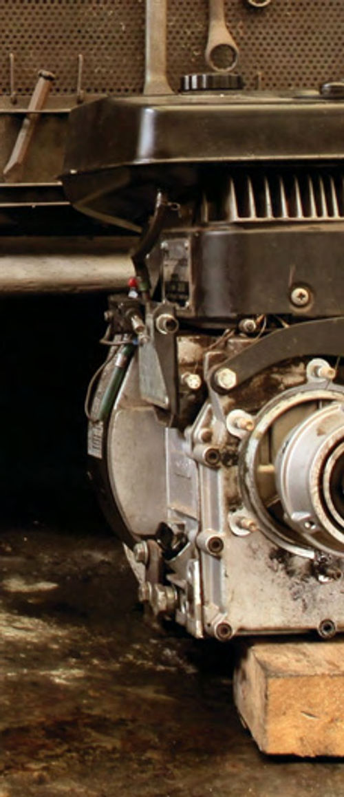
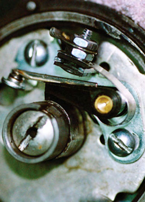
Always install large cables(heavy duty, one gauge or larger). Also, install a “redundant” large one-gauge ground cable connected at the original ground point on the frame cross member and routed over to the emergency brake bracket bolt. (See Photo 1.)
The benefits include a very fast cranking speed and good ignition primary voltage during cranking.
Most Model A’s with the above setup will crank at 5.2 volts or more (measured at the battery).
The result is a cold (well-tuned)Model A Ford engine will start in one second after cranking begins. A warmed-up Model A engine will start in less than a second once cranking starts.That’s Fast!
Small Cables: Small cables (4-6 gauge) will get hot during cranking and ruin starter switches resulting in burned starters.
A 12-volt battery is unnecessary. We’ve found that 12-volt batteries will damage Bendix drives and springs, and will grind off starter ring teeth.
An 8-volt battery is unnecessary as well. The 8-volt batteries never get fully charged on a six-volt generator. And if you boost the 6-volt third brush generator to charge at a higher voltage, the generator will burn up in time and light bulbs will burn out.
We’ve found that a well-maintained 6- volt system works very well.A 6-volt battery’s “rest” voltage should be 6.4 at full charge. Cranking voltage should be 5.2 volts. Ground voltage, during cranking, should not exceed 0.3 volts. Charging voltage should be 7.2.
All of these readings can be measured at the battery. The ground voltage is measured from the battery (+) post to an engine ground while cranking the engine with the starter.
Good digital voltmeters will work when cranking. If the engine is running, you may have to use an analog (needle type) voltmeter. RF (radio frequency) “noise” may mess up a digital meter.
How-to measure battery and cranking voltages are outlined onmyWeb site, milttheinstructor.com, under“technical” tips.
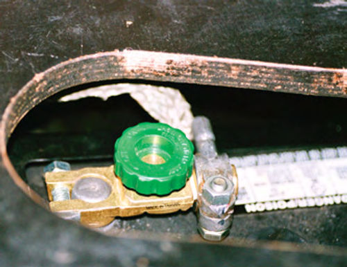
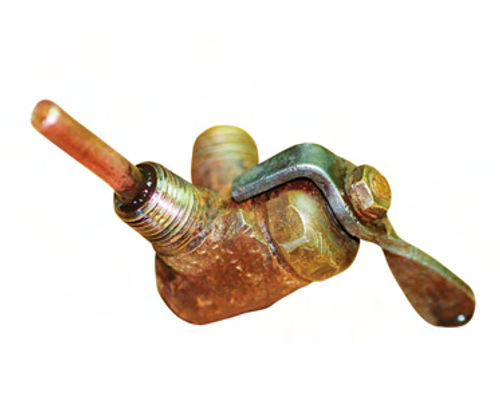
For safety’ssake, install a battery quick disconnect on the ground battery post. (See Photo 2.) Disconnect the battery when parking overnight as this helps to prevent electrical fires.
Engine Condition
Before beginning the tune-up, change the crankcase oil and test the engine compression.
Note if any water comes out of the crankcase drain hole before the oil starts draining out. When draining the oil, a few drops of water are OK. This may have been caused by condensation during long-term storage. But if there’s a cupful of water, internal leaks due to block cracks or blown head gaskets may be the cause.
If the oil being drained is “milky” in appearance, there’s definitely an internal coolant leak. It may be a block crack and/or a blown head gasket.
At this point, the coolant leak sources should be diagnosed and corrected prior to the engine tune-up.

Apply a small amount of “gasket maker” to the pan plug gasket and install the pan plug.
Add four quarts(Model A Ford) of 20- 50 wtAP ISMoil to the crankcase.Check the oil level and top off to the top mark on the dipstick.
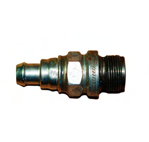
Compression Test: Remove the spark plugs and conduct a “dry” compression test. Fabricate an 18 mm spark plug thread adaptor to fit your compression gauge. (See Photo 3.)
Crank the engine using the starter to “bump” the gauge four times during continuous cranking. Record the compression readings.

The minimum cranking compression pressure should be at least 60 PSI and even within ±5 PSI on all four cylinders.
If one cylinder is zero, service the valves. One valve may be stuck open.
If two adjacent cylinders have low compression (like 30 psi), the head gasket may be leaking between those two cylinders.
Now conduct a “wet” compression test. Squirt motor oil into each spark plug hole four times (four oil can strokes) and crank the engine for 30 seconds to spread the oil all around the pistons and rings. Retest the compression during cranking as outlined above.
Long storage periods(years) may have allowed the oil to “congeal” on the cylinder walls and piston rings. I have experienced 20-30 PSI increases using the above technique. After startup the engine may smoke for 30 minutes.
Recheck the compression after one hour of running. If the pressure increases at least 10 PSI or more above the dry compression reading weak piston rings may be suspected.
If your dry compression test is below 50 PSI the engine may not start even after a tune-up. Additional engine diagnosis and repairs may be in order.
Repair compression losses prior to the tune-up, and recheck the compression.
If the compression is 60 PSI or more and even, continue with the ignition and fuel system tune-up.
Ignition Tune-Up
The ignition tune-up includes testing the ignition switch, Ohming out the shielded primary lead, servicing the point ignition distributor, replacing the spark plugs, and adjusting the ignition timing.
Distributor Service: When removing the distributor, note the distributor body set screw and jamb nut. Was it tight? If it’s loose and/or the distributor body is loose, the primary circuit ground may be bad resulting in blue/black or severely pitted points.
In addition, note and clean the distributor body mount portion and the mount hole in the cylinder head. All rust scale must be sanded (80-grit) and cleaned with solvent (paint thinner) to shiny clean.
Disassemble and clean the body, then lube the shaft with motor oil.
Install new points and condenser. Insulate and position the primary lead-in wire so it will not kink when retarding or advancing the distributor plate. (See Photo 4.)
Make sure the points contact “squarely.” Adjust the point gap to 0.022 inch. This allows for some “wear in” of the point arm rubbing block.
Smear a light coat of moly grease or cam lube onto the distributor cam.
Primary Lead Test: With the key off and the primary lead removed from the distributor, test the resistance between the wire and the outer metal shield. Hook up a digital ohmmeter set to the highest scale. Connect one test lead to the primary lead tip. Connect the other clip to the outer metal casing. Leave the ignition key in the off position.
The ohms should display 1 or 0L (infinity) on the 20 megohm (or higher) scale. If so, this proves there’s no short between the primary wire and the outer metal shield.
If the ohm reading is less than 20 megohms(like 1000 ohms), the primary wire is shorted to the outer cable. Replace the primary wire and cable.
Key Switch: Old key ignition switches wear out mechanically and electrically. When the distributor is out and disconnected from the primary shielded lead, hook up one voltmeter test lead to the shielded primary wire tip end and the other test lead to ground. Turn on the key. The voltage should read 6.3. Next, wiggle the key to simulate vibration. Make sure the voltage remains steady at 6.3.
Then slowly turn the key toward “off.” Note the key position when the voltage drops to zero. If you turn the key 1/8 or 1/4 turn, the switch is OK. If the voltage drops to zero just as you start to turn the key off, replace the switch.
Spark Test: Prior to installation of the distributor, screw the shielded primary lead into the distributor body. (See Photo 5.) Ground the distributor to the engine with an alligator clip test lead. Hold the coil wire 1/4-inch away from the distributor body surface. Turn on the key. Have your helper spin the distributor shaft counterclockwise. You should get a fat blue spark.
Move the coil wire to a 3/8-inch gap. It should still produce a spark.
Ifthistests out OK, install the distributor. Note: If you get shocked while holding the coil wire during this test, replace the coil wire!
If the spark is weak, recheck the point contact and gap.
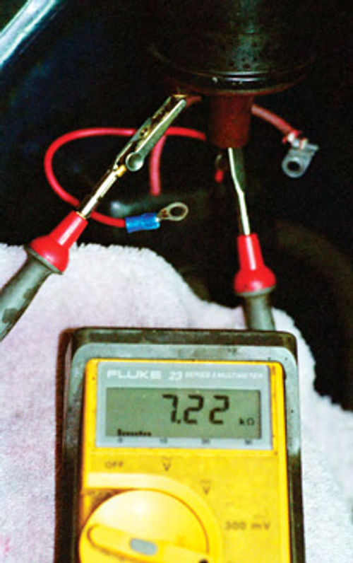
Disconnect the coil wiring. Ohm the coil. The primary coil winding, between the two primary wire studs, should read around 1.5 ohms on a 6-volt coil. The secondary lead should read 6000 to 10,000 ohms. This is measured from either primary wire stud to the secondary coil tower.
A digital ohmmeter is required to get the accuracy on the coil primary winding. (See Photo 6.)
If the ohm readings are higher or lower than the above readings, replace the coil.
Distributor Installation: As noted above, the distributor mount hole must be clean. Then install the distributor into the block.
The distributor shaft slotis “off-set.”As you install the distributor, turn the shaft until the distributor body “drops in.” Make sure the body pin is in its place and the body is seated on the head surface.
Install the setscrew. Torque with a large screwdriver; jamb the lock nut too tight.
Turn on the key and crank the engine with the coil wire 1/4 inch from the manifold surface. Make sure the spark is as good as your pre-installation spark test.
Ignition Timing: Position the number 1 cylinder at TDC on the compression stroke using the timing pin indent. Crank the engine until the pin drops into the timing gear indent.
Then put the transmission in high gear. Push the car backward until the timing pin just passes the indent. Then push the car forward until the pin drops into the indent.
Retard the spark lever (up). Loosen the distributor cam screw. Rotate the cam until the rotor slot is at the 4 o’clock position. Rotate the cam counterclockwise until the cam lobe just starts to open the points with the rotor notch at the 4 o’clock position. Tighten the cam lobe screw. (See Photo 7.)
Spark Plugs: Gap the new specified spark plugs to 0.035 inch. Sparingly apply Never Seez to the plug threads. Install the plugs by hand until the plug and gasket just seats. Torque to 1/4-turn past seat contact.
Fuel System
The fuel system checks include the fuel tank, clean gas flow, carburetor service, and adjustments.
Gas Tank: Inspect the gas tank’s innards using a flashlight. Look into the tank (inside bottom) toward the fuel shutoff valve opening. Note if there’s a clean surface or residue around the opening.
If there’s residue (like around 1/4- to 1/2-inch deep), you may try to install a shutoff valve with a one-inch “stand pipe” to get above the residue. (See Photo 8.)
Keep in mind, however, that the best way to end up with a clean tank is to remove it and have it professionally cleaned and repaired.
Fuel Flow: After inspecting/repairing the fuel tank, test for fuel flow through the shutoff valve, sediment bowl and the fuel line.
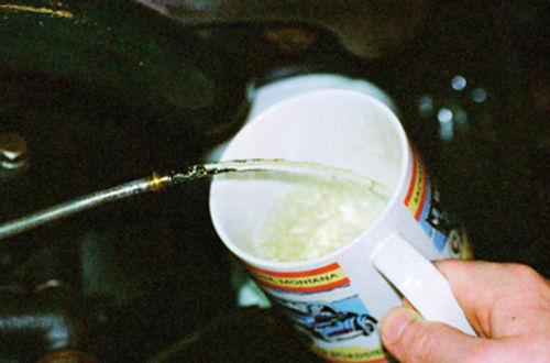
Disconnect the fuel line at the carburetor. Set a plastic bucket on the floor with the gas valve off, add one gallon of gas to the tank. Turn on the gas valve and observe the fuel flow. It should flow with a stream extending six inches beyond the gas line tip.
If the flow is weak or dribbling, drain the gas at the shutoff valve. Locate the restriction(s) and repair. Re-assemble and test flow the fuel stream again. (See Photo 9.)
Carburetor Service: The most common failures in a Model A Ford Zenith carburetor are due to a lack of maintenance or improper adjustments. These include the carburetor strainer assembly, jet orifice diameters that are of the wrong size or not positioned correctly, incorrect float height, and/or mis-adjustment of the fuel adjusting needle (on the choke lever), and the mis-adjustment of the idle air mixture screw.
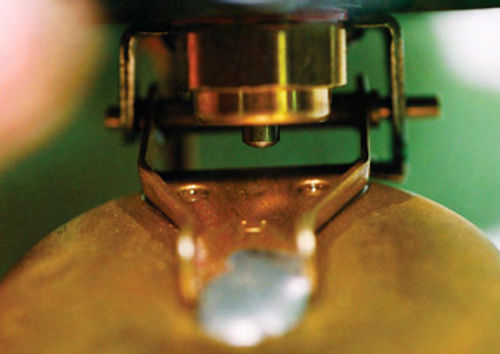
The float must be inspected to ensure that there are no float leaks and/or that the float needle is not binding. (See Photo 10.)
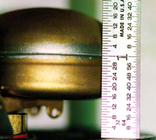
On Zenith carburetors, the float height must be one inch, as shown in Photo 11.
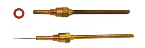
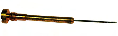
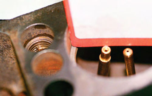
All jets must be unplugged and properly sized. (See Photos 12 and 13.)
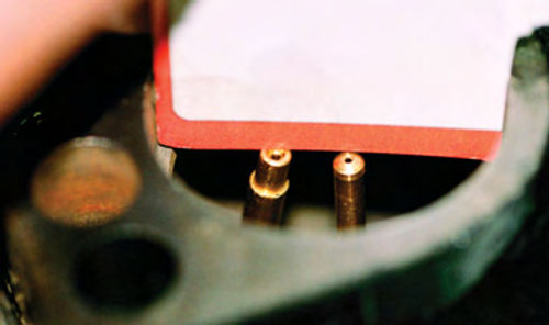
The main jet and cap jet must be positioned equally in height with respect to the venturi minimum diameter. (See Photo 14.)
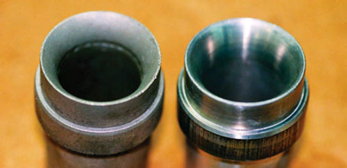
The venturi must be smooth. (See Photo 15.)
Note: Many Zenith carburetors drip when setting. All the above “what ifs” and the “how-to’s” will stop the drips.
Next time, we’ll resume our Model A maintenance project with the braking and steering systems.
Resource
Model A Ford Mechanics Handbooks
by Les Andrews
Cottage Hill Publishing
voice/fax