
Makin’ Them Roadworthy Prep Your Model A for Touring, Pt .3
In This Final Installment, We’ll Check Knocks, Charging & Shocks. Then We’ll Take a Drive and Test Our A’s Performance.
EDITOR’S NOTE: THROUGHOUT this three-part series we’ve been highlighting prep work that will keep you on the road while touring with a minimum of downtime. This month we’ll look at the engine, charging and cooling systems, shocks and tires and then apply our discussions to a test drive and a couple of case histories. And for more on making your vintage vehicle a reliable driver, see page 22. So far we’ve had 19 images in the series, so we’ll start here with Photo 20.
Engine Rod Knocks
After tuning the engine for smooth running (timing and mixture, see the July issue) test for rod knocks. Open and hold the throttle steady at around 1000 rpm. Listen for a “rap;” then short out one plug at a time. If there’s a rap and it goes away during the cylinder shorting, a slight rod knock exists. Continue this test on the other three rods.
Recheck for rod knock after a long warm-up. If the rod knock does not exist now, the rod is just slightly loose. If the rod is still knocking, it’s very loose. Diagnose, repair and adjust all rods. Then retest to be certain that the rod knocks have been eliminated.
If you adjust the rods, use Plastigage to establish the bearing clearance. Remove one shim (.002-.003 inch) at a time. Recheck clearance, squishing the Plastigage out.
Charging System
Model A Ford Generator: Check the amp meter on the dash. The original 6-volt generator with a cutout is a “3rd brush regulation” type. When revved up, the charge rate should read 5-10 amps; this is adequate for daytime tour driving.
If it’s charging at 15 amps, this is OK. However, be aware that the commutator will turn purple in time from these conditions and may stop charging.
Alternator, 6-Volt: For touring, I recommend a 6-volt alternator. If you’re looking for thousands of miles of durable touring, invest in a 6-volt alternator, one wire hook-up. The charging rate is around 7.2 volts. An alternator will charge at idle.
I’ve found that L.D. Becker Auto Electric produces very good alternators (419- 668-5986;Box 624, Norwalk, OH 44857). These units are 6-volt positive ground.
Cooling System
If radiator boiling occurs within the first half-hour of running the engine, service the cooling system by installing Prestone Super Flush. Leave it in while road testing.
Note: If it boils over during the road test, top off with water, keeping it full. The engine will not burn up.
Drain and flush twice with clear water. Fill the system with clear water and add a “coolant wetting” additive like one cup of soluble oil (from NAPA or Carquest).
In an “open” (no pressure) radiator system, the coolant level will always be around 1-2 inches below the top after some touring.
If your Model A boils over during the road test, you’ll need to install a new “flat tube” radiator.
If your Model A runs real cool (warm to the hand, touching the upper radiator hose), you may want to consider a 160° F thermostat available at most Model A parts houses.
In freezing climates, you may want to add antifreeze coolant, or drain the coolant for the wintertime.
Tires
If the tires are more than 10 years old, replace them along with new tubes.
We have seen 1950s-era “nylon” tires with flat spots and out-of-round by 3/8- inch, causing severe shaking on the road.
Shocks
Install new shocks. Rebuilt originalstyle shocks work very well.
Tubular shock kits are available from Model A parts stores. The shocks will improve the “driving feel” and help maintain control on the road.
Road Test
Now, you’re ready for your first drive. Bring a helper along to keep notes regarding the following items:
Engine Startup: The engine should start in one second during cold engine cranking, and 1/2-second from the start of cranking on a warmed-up engine.
Clutch: Does it release during shifting or is there chattering during takeoff?
Cruise: Is there bucking, surging at steady throttle (35 mph).
Acceleration: Good power or surging?
Overheating: If it’s boiling over; keep it full of coolant (as stated above).
Smoke: Look for black smoke (rich) or white smoke (oil).
Note any “sweet smell”in the exhaust. If you use glycol coolant, a sweet smell indicates an internal engine combustion leak.
Service Brakes, Mechanical: At 15 mph, apply brakes gently to slow down.
Do the brakes pull right or left?
Do any of the four brakes lock up?
Drive the car at 35 mph. Hold onto the steering wheel and warn your helper of an impending “panic stop.” When traffic conditions permit, slam on the brakes to lock the wheels.
Note any hard pull to the left or right. As discussed earlier, rear brakes lock up prior to the front brakes. Also note if there’s no lockup. Does your Model A stop quickly in panic braking?
No Brake Lockup: If there’s no brake lockup, drive the car 100 miles and perform this “minor” adjustment.
Lift the car off of the floor, clearing all four wheels. Adjust the backing plate adjustment screws inward (clockwise as you look at the screw head). Adjust screw inward to lock up drum, then back it out (counterclockwise) six notches.
Apply the brake pedal two inches.
Back brakes should drag slightly more than the fronts. Side-to-side drag should be equal.
Apply brakes three inches; the wheels should be locked up
Emergency Brake: With wheels off of the floor, pull the emergency brake lever to three clicks back. The rear wheels should be locked up. Apply lever to two clicks and check for heavy equal drag side-to-side.
Then road test at 15 mph. Pull lever to three clicks. The rear wheels should lock up and stop the car in a straight line.
If you have hydraulic brakes: Check for pulling side-to-side.
Lift the car off of the floor. Adjust each brake shoe to lock; then back off until it’s just free.
Push the brake pedal and release it.There should be no drag. Ifit drags, check wheels and master cylinders. Repair for complete release. Bleed brakes to clear air bubbles.
Now let’s take what we’ve discussed so far and apply it to a couple of Model A case histories.
Case History 1: A “Driver” Restoration of a ’29 Model A Ford Coupe
The current owner rode all around Minnesota in this Model A decades ago when he was just eight years old.
The car eventually showed up in Portland, Oregon. The owner discovered that an old friend had brought the car from Minnesota to Portland and he talked him into selling it.
This Ford Model A then wound up in Sacramento and the new owner, Wayne Judd, began a “driver” restoration process, a popular approach.
To begin the restoration, he decided to have the engine, clutch and transmission overhauled (due to low compression and a chattering clutch).
The frame was changed because it had been modified. The front mount did not line up with the crank handle.
One year later, it was time for the final tune-up, brake adjustment, and front end toe-in adjustment.
This section outlines correct and incorrect mechanical service, adjustments and repairs performed on this car.
The starting, ignition, carburetion, charging, steering and brake systems were serviced.
Service, Repairs and Adjustments
Here’s what we found on several tuneup items: Sitting for long periods takes its toll, plus there had been some incorrect service on the ignition, carburetion, steering and brake systems.
Cranking System: After servicing, the 6- volt cranking system performed very well. The battery “rest voltage” was 6.2; the cranking voltage was 5.2. The ground voltage during cranking was 0.2 volts. All these readings are acceptable for a 6-volt system with clean joints.
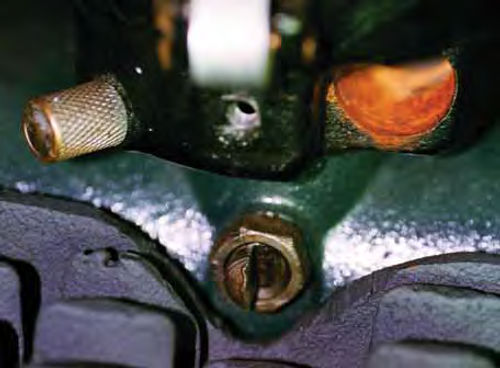
On this ’29 Model A we installed a redundant one-gauge ground cable with eyelets at both ends routed from the frame to the emergency brake bolt. This provides a better ground backup in the event the frame grounds and joints rust up with time. (See Photo 20, originally printed as Photo 1 in the July issue.)
This redundant ground will “wake up” a 6-volt system without ruining the starter Bendix, or the flywheel gear teeth.
Engine: The oil was changed. There was no water in the oil. This verifies no internal coolant leaks (head gasket, cracks).
The head bolts (nuts) were re-torqued to 55 ft.-lbs.
On this ’29 Model A, the dry cranking compression was 88 PSI on the number 1 cylinder, 90 on #2, 90 on #3 and 91 on #4. Very good!
We guessed the stock-looking head had been milled and/ or dome pistons may have been installed.
The bottom line here is this engine is an excellent candidate for continuing the ignition and carburetor tune-up.
Ignition: The plug gaps were correct at 0.035 inch. Number 1 and 4 plugs were slightly sooty.
The plug threads were lightly coated with Never-Seez, re-installed, and torqued 1/4 turn past the spark plug gasket contact.
Distributor: The distributor body set screw was loose. Upon reinstalling the distributor, the broken set screw was tightened and the lock nut was jammed.
The distributor body set screw must be tight to provide a good electrical ground back to the battery (+) post. (See Photo 21.)
If the ground connections are loose, rusted or corroded, the points will burn up, turn purple (hot), and become pitted. These conditions eventually result in hard starting and/or an ignition misfire.
The points in our ’29 Model A were gapped at 0.015 inch and there was no cam lube.
No cam lube leads to the points closing up and retarded timing due to the point rubbing block wearing excessively.
The point contacts were smooth and gray. They were adjusted to a 0.022-inch gap. Cam lube was applied sparingly.
In addition, we rotated the distributor cam to all four lobes and the point gap was the same (0.022 inch). This provides “equal dwell” for all 4 cylinders resulting in a smooth idle (with good even compression and correct idle mixture).
With all the above corrections, we obtained a good strong blue 1/4-inch spark during cranking.
The last check on the ignition system was to verify the key switch and the metal-covered cable were insulated from the primary wire to the distributor.
To accomplish this check, open the points and leave the key off (open circuit). Hook up a digital ohmmeter and switch to the highest scale (20 megohms). Hook one alligator clip to the point nut and the other to the metal cable. The ohm reading should be 1 or 0L (infinity) on the 20 megohm scale. This proves insulation of the primary lead to the distributor is OK and not shorted. Recently (on another Model A)I measured a shielded primary cable. It measured 600 ohms using the above hookup. The engine would start and then die because the spark “quit.”
With a new primary lead tested as outlined above, that car ran fine.
The key switch can be tested by opening the points, hooking up a digital voltmeter, and turning on the key. The meter black (-) test lead should be connected to the point post and the red (+) test lead should be connected to the ground. Turn on the key. Do not start the engine. The reading should be the same as battery voltage (6.3 volts full charge).
Next wiggle the key to simulate vibration. The voltage should stay at 6.3.
Then, from the key-on position, turn the key slowly towards off. Note the position of the key as you turn it off. When the voltage drops to zero (0) from 6.3, this is the position the switch “opens” the circuit. Normally, you will turn it at least 1/8 turn before the voltage drops to zero.
If it drops to zero immediately upon turning the key, replace the switch.
This ’29 Model A passed the key switch test.
Note: If your A is equipped with a 12- volt negative ground system, ground to meter the negative (-) test lead. Connect the red test lead to the same points as listed above. The 12-volt measurements should read 12.6 on a fully charged 12- volt battery.
Ignition Timing: After reinstalling the distributor with the correct point gap (0.022 inch), remove the timing pin and re-insert the round end through the timing pin hole.
Crank (bump) the starter until you feel the pin jump into the timing gear indent. The engine will turn past the timing gear indent. Put the transmission in high gear and push the vehicle backwards just until the pin drops into or turns past the indent. Then, push the vehicle forward slowly until the pin drops into the indent. This positions all the gears as if the engine were running and positions the #1 cylinder at top dead center
Put the transmission in neutral. Retard the spark lever (up).
Loosen the distributor cam screw. Rotate the cam counterclockwise until the points just start to open with the rotor notch pointing toward #1 in the distributor cap (4 o’clock position as you look at the distributor). Tighten the distributor cam screw.
Fuel System
Gas Tank: On this ’29 A, the gas tank was replaced after obtaining a good used one. The owner had it professionally cleaned, repaired and sealed.
The gas flowed through the sediment bowl clean with a 12-inch flow stream.
Carburetor: The Zenith carburetor had been “rebuilt” on this A. We’re not sure to what extent, but this was what we found right and wrong.
The carburetor was “flooding” out the bowl cover prior to disassembly.
When the owner drove it home, he complained there was no power and it would not idle unless he opened the throttle lever some. He also could smell gas when he left the garage closed up. A very dangerous situation!
The carburetor was disassembled and cleaned in carburetor cleaner.
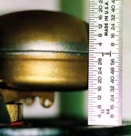
Always test the float needle for binding. Test the float for leaks. The float level was correct at one (1) inch from the top surface to the float seam. (See Photo 22.)
The idle jet was plugged; it looked like old gas residue was the culprit. The main jet also was plugged solid with old gas residue. This adds up to no power and no idle. Both jets were unplugged. All other jets were checked and found to be the right size.
In addition, the jet height (tips) on Zenith carbs must be equal and the tips positioned at the minimum diameter of the venturi.
The idle jet seat was machined flat and had a gasket for a seal. It was replaced with a “tapered” seat idle jet and correct diameter orifice of 0.021 inch (#75 drill bit).
A new float needle and seat was installed.
The gas adjusting needle was pre-set one turn open, and the idle mixture screw was preset at 11 ⁄2 turns open.
Steering
On this ’29 A the front end toe-in was a major 3/4-inch. The specification is 1/8-inch toe-in. The toe-in was then readjusted to specification.
All joints and nuts on the front end were tight and lubricated.
Brakes
There were the usual complaints, “it doesn’t stop” and/or “it pulls” to the right (or left) when putting on the brakes.
The front lever angles were not the same. One was forward (OK, Photo 23) and the other was straight up (Not Good).
Unequal lever angles cause unequal mechanical advantage and can lead to pulling right or left.
With the wheels and drums removed, we found new bonded lining and smooth drums. I trust this lining is “soft” because the “hard bonded” modern lining may groove the drums. After inspecting the brake linkages for correct action the drums were reinstalled.
The brake rods were disconnected and the linings on each wheel were adjusted to a very light drag.
The front levers were still unequal. So off came the left front drum. A brake operating pin shim was installed between the wedge and the brake operating pin. A shim is a small 3/8” diameter core plug. Shims are available from Model A Ford parts stores.
Upon adjustment of the left drum again, the front brake levers were equal and tilted forward about 3/8” from the lever pivot point.
The rear brake cam and levers were at the correct angle and equal.
The cross shaft arms were vertical, with our foot off the brake pedal. This is correct on a Model A Ford.
Next, all brake rod clevis yokes were adjusted to fit the angled levers front and back.
Then we applied the brake pedal, one inch, two inches and three inches. The drum drag was compared by rotating the wheels front to back, and right to left.
A little more drag on the rear than the front is specification on a Model A Ford.
All the rods, clevis yokes and jam nuts originally were loose. After adjustment, the jam nuts were tight and new cotter pins were installed.
Engine Startup
The newly rebuilt and tuned engine started in three seconds with a quick closing of the choke.
After adjusting the idle screw to best idle with the gas adjusting needle at 1/2- turn open, the engine was purring and idling smoothly. It was snappy upon throttle opening. This engine now starts in 1/2-second.
We tested the engine for rod knock by revving the engine to around 1500 RPM steady state and shorting out one spark plug at a time. There were absolutely no rod knocks or rapping. And it runs beautifully smooth.
Road Test

The clutch (V-8 plate) releases very well and operates very smoothly. The acceleration was better than a standard Model A Ford. There was no surging and lots of power.
The brakes stopped this Model A Ford straight and quickly.
I explained, with a minor adjustment after 100 miles of driving, that the mechanical braking will improve when the brake linings seat in.
Owner’s Comment
“It runs great, idles good, lots of power, and now it starts right up. It used to grind for a long time to start.”
Note: This Model A Ford is equipped with a 6-volt, group 1 commercial battery, 650 cold cranking amps. There’s no need for an 8- or 12-volt battery. Clean joints, 1-gauge cables, and a redundant battery-to-engine ground are adequate.
Case History 2: Incorrect Repairs on a Model A Zenith Carburetor
I recently cleaned and “re calibrated” a Zenith carburetor for a ’29 Model A Ford Tudor Sedan. The carburetor was “flooding” prior to removal. A light tap of a hammer stopped the flooding. Note: Tapping the top of the carburetor sometimes will allow debris to flow through, letting the needle seat. This symptom is a clue to inspect the fuel supply lines and fuel tank for cleanliness. In some cases, the flooding may be caused by a worn-out needle and seat.
The spark plugs were black on the inner porcelain.
Here’s a list of what was right and wrong with this carburetor:
• The filter screen in the carburetor was very clean.
• The float level was 1 1 ⁄8 inches. The specification here is one (1) inch. This would tend to lean the mixture for all carburetor circuits.
• The secondary well jet was loose and may have been causing a slightly rich mixture.
• The main jet was 1/32 inch above the venturi’s minimum diameter. This reduces venturi vacuum and may cause a leaner than normal mixture.
• The cap jet was at the correct height, level and even with the minimum venturi diameter.
• The inside of the carburetor looked brand-new. This may have been a reproduction carb.
• The venturi was “pitted” around the circumference at the minimum diameter.
• Most all of the jets were out of specification. Idle jet measured 0.021 inch (#75 drill bit). This is correct. Cap jet measured 0.039 inch, #61 drill bit; spec is 0.37 inch, #63 drill bit. Main jet measured 0.039 inch, #61 drill bit; spec is#63, .037 inch. Compensator jet measured 0.38 #67 drill bit; spec is #65, .035 inch.
Needless to say, all of the jets except the idle jet were oversize from 2-3 thousandths of an inch, causing richer than normal mixtures.
The jets in a new carb kit were also out of spec. However, the kit main jet was 5 thousandths under specification. I drilled this new kit main jet to spec #63, 0.037 inch. The other jets were oversize from 2- 3 thousandths inch.
The carburetor was reassembled with a new needle valve and jets that were closest to specification. The float was readjusted to 1 inch as specified. The idle mixture screw was preset to 1 1 ⁄2 turns from seated. The gas adjusting needle (on the choke linkage) was adjusted (preset) to one turn open.
The customer installed the carburetor and after minor adjustments the engine idled very smoothly. This Model A Ford performed very well with no hesitation from takeoff, 1/2-second startup, no drips, no flooding, and no surging in 2nd gear at wide open throttle (40 mph).
Resources: Sacramento Vintage Ford
2484 Mercantile Drive
Rancho Cordova, CA 95742-6216
Bratton’s Antique Auto Parts
1606 Backacre Circle
Mount Airy, MD 21771
Snyder’s Antique Auto Parts
12925 Woodworth Road
New Springfield, OH 44443


