
Makin’ Them Roadworthy Getting a ’40 Buick Ready to Cruise
There Are Numerous Misconceptions About Octane Ratings. So, We Asked a Chemist to Discuss the Subject.
Sometimes, I try cranking several times to start the engine when cold,” the owner of the 1940 Buick reported. “It finally starts. After warm-up, the engine surges while cruising and idles rough.”
I suggested a thorough engine tune-up including servicing the starting system, a compression test, adjusting the valves, servicing the ignition system, performing tests on the fuel system and the carburetor, start-up tests, running tune-up adjustments, and a road test.
Here is how we approached and serviced these tune-up components:
About the Car In Question
This collectible is an “original” 1940 Buick Super with a 248 cid straight 8 engine, a 6.1:1 compression ratio, and it’s equipped with a 2-barrel Stromberg carburetor.
The odometer showed 24,000 miles. However, the brake, clutch and accelerator pedals showed major wear, so it’s more like 124,000 miles.
The seat upholstery was worn; the headliner looks new. The exterior chrome and paint are in good shape.
It’s Had Some Care
The current owner is the third owner of this car, and the second owner was an auto mechanic. Previous records showed lots of maintenance services including major brake repairs such as brake linings, brake cylinders, master cylinder work, and flex lines.
The current owner wants to service this collectible so that he can drive it on tours, go to cruise nights and car shows…and feel confident it will make it.
The Starting System
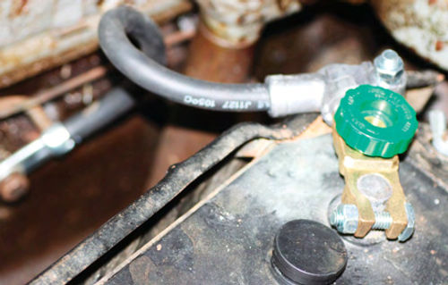
A new group 2E 6-volt battery had already been installed. The original cables were replaced with one (1) gauge cables, because the cable battery end connectors were corroded and the bolts and nuts were frozen.
A quick disconnect was installed on the battery’s negative post (ground). (See Photo 1.)
After the starting system service, the battery “rest” voltage was 6.3.The cranking voltage at the battery was very good at 5.5 volts. The ground voltage was good at 0.1 volt measured at the battery.
This cranking system sounded very energetic, like it wanted to startright up. But it’s not time for that yet.
The oil and filter had already been changed. New 20-50 wt oil was installed prior to the tune-up.
There was no water in the old oil. This is a fair indicator there were no internal cracks or a blown head gasket around the water ports.
The spark plugs were removed and a “dry” cranking compression test was performed. The measurements were: 85, 80, 80, 80, 80, 60, 75 and 85 psi on cylinders 1 through 8. Not bad for a 6.1:1 compression ratio.
Cylinder 6 does show lower pressure at 60 psi. This may be caused by a burned valve, incorrect valve lash, marginal piston ring seal,or a “sticky valve.”
We opted to continue the tune-up because these compression readings are good enough for a start-up.
Later, during the tune-up, we adjusted the valve lash (cold engine), just to make sure the valve tappet clearances were not too tight. The valve tappet clearance specification is 0.015-inch on this 40 Buick Super.
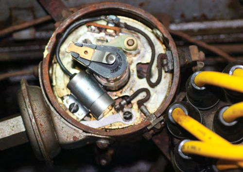
The valve clearance was measured at TDC (top dead center) on each cylinder. Starting with the distributor rotor pointing at #1 in the distributor cap, we adjusted each set of valves (intake and exhaust) to a 0.015-inch gap, following the engine’s firing order.
After adjusting the valves in the #1 cylinder, the starter was “bumped” to cylinder 6, which is next in this engine’s firing order. See Photo 2 for more on making the valve adjustments.
Each distributor rotor rotation to the next cylinder is 45º (360º ÷8).
Most of the valves had been adjusted too tight, measuring 12-14 thousandths of an inch. The Number 8 cylinder intake valve was very loose at 0.020 inch.
After engine start-up and warm-up, the valve lash was rechecked while idling. Two valves were slightly loose and readjusted to 0.015 inch.
After startup, the clicks were minimal and we could not hear any clicks with the valve cover installed.
The Ignition
Ignition services included checking the ignition switch, spark plugs, wires, point gap, condenser, mechanical advance and the vacuum advance.
We tested the ignition switch by opening the points and hooking up the voltmeter at the points and to battery ground. Turning on the key switch, the open circuit voltage with the points open should read the same as battery voltage (6.3).
On all switches also wiggle the key to simulate vibration; Turn on the switch, and then turn it off slowly to see when the voltage droops from 6.3 to 0.
A good switch will usually drop to 0 after turning it toward “off” around 1/8-turn.
On this collectible, we found the voltage was intermittently 0 and 6.3 when turning the key switch on with the points open.
As the key was on longer for other tests, the voltage became more steady at 6.3 with the points open.
I believe the switch was “warming up” as we were checking for spark later during the ignition service.
I advised the owner to replace the ignition switch and that this component may be the major cause for the “hard start” with a cold engine. Remember to always test the ignition switch on your collectible vehicle at every tune-up. After all, in this case the switch is 70 years old! It’s time for a replacement.
The spark plugs had been removed to test the compression. All were tan-orange on the inside porcelain surface. This is normal, showing us the carburetor mixture was “in the ballpark.”
Had the spark plug inside porcelain surfaces been black and sooty, the carburetor mixture would have been rich.
On this running collectible, the plugs looked new and were all gapped at 0.035-inch. The specification, however, is 0.025-inch so all plugs were re-gapped to that measurement.
As an aside, if your collectible has been setting for 30-40 years, install new specified plugs.
The Buick’s plug wires were “resistor” type and measured from 50-75 thousand ohms. Not Good!
New resistor wires measure around 3000 ohms per foot and are OK for our collector cars, resulting in a good spark.
Old wires can also “arc” to ground leading to ignition misfire.
New wires are recommended when covered up with panels (our ’40 Buick) and those routed inside metal tubes (like flathead Ford V8s and other collectibles).
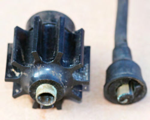
We opted to replace the plug wires with a CarQuest “universal” set of “stranded” wires as was used on the original ignition systems. All the new wires measured 0.1 ohm.
Always, always check new plug wire resistance. It’s possible to have a terminal “open” electrically on the spark plug end or the distributor end. This will lead to ignition misfire. (Photo 3 shows you how to measure spark plug wire resistance.)

Note: The coil wire had an aftermarket intensifier at the coil end. Not good! The resistance on this unit was one million ohms!I believe this unitisbuiltlikea transformer.My “old time experience” is that these units fail, causing ignition misfire.
A new “stranded” coil wire was installed and the “intensifier”was left out.
Here’s the deal. You want all the coil voltage available to jump both the rotor gap and the spark plug gap and start ignition combustion, and that’s all.
Bad wires and intensifiers just increase normal voltage readings. (See Photo 4.)
The ignition points were new and just slightly gray. This is normal.
The distributor cam had a hard, caked grease-like film.
The point gap was 0.013-inch and the spec is 0.016-inch, so the points were readjusted to 0.016-inch. Cam lube was applied to the distributor cam.
Note: More often than not, the distributor cam is dry and the point rubbing block wears prematurely. Always apply cam lube or a light coat of moly grease. Rotate the distributor cam by cranking the engine. This will reduce wear on the point rubbing block.
The mechanical advance was free. It was checked with the engine off by rotating the rotor. I could feel the spring action of the weights as I let go of the rotor. The rotor would advance around 10º which is 20º on the crankshaft.
We applied three drops of motor oil on the “wick” under the rotor. This keeps the distributor camshaft free on the distributor shaft. This Is necessary for good mechanical advance operation.
The vacuum advance was checked by disconnecting the small vacuum line, holding my thumb over the end, advancing the plate, then letting it go. You should feel a slight vacuum (pfft) as you let go of the distributor vacuum advance tubing connector.
If there’s no vacuum, replace the vacuum advance unit. Most often, you must supply the parts distributor with the make and part number to obtain the correct vacuum advance unit.
If one is not available, the vacuum advance diaphragm can be replaced by S and N Auto Electric in Sacramento, California, (visit snautoelectric.com).
Old vacuum advance diaphragms may crack when your collectible is on the road, while good vacuum advance units result in better gas mileage and part throttle acceleration.
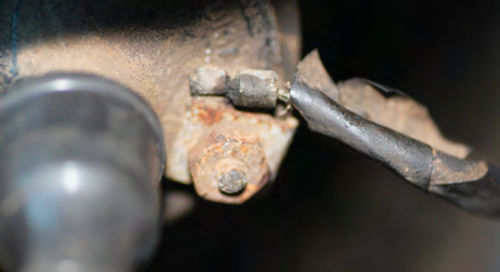
One last item serviced on the ignition system was the coil primary hot (+) wire. It was attached to the connector with only two wire strands.
The terminal was replaced after cutting off the primary wire 1 inch from the connector. (See Photo 5.)
After all the above tests, we achieved a sharp blue spark out of the coil wire that was 3/8-inch long (distributor end) while cranking with the key on.
The Fuel System
First, check the fuel tank. If your collectible has been sitting for more than one year, remove it and have it professionally cleaned. Blow out the fuel line, and replace the flex line.
Then test the fuel pump for pressure and flow while cranking.
Disable the ignition by grounding the coil wire, distributor end. Hook up a vacuum/pressure gauge at the carburetor fuel inlet. For safety, place a fire extinguisher near the car.
Crank the engine for five seconds. The fuel pressure on our Buick read 4 1 ⁄2 PSI; very good.
Next, hold a 1-quart plastic bottle over the fuel line, do not use foam cups as they’ll melt, and then crank the engine for five seconds.
Our Buick pumped five strong squirts of gas into the plastic bottle. This is a good flow.
Note: If the car has been in storage for a long time, replace the pump. Over long periods of time, the diaphragm deteriorates and may stop working or leak when the vehicle returns to operation.
I recommend changing the fuel pump and the flex line every five years.
Next, check the carburetor with the engine off. This’ 40 Buick Stromberg carburetor has an automatic choke and was originally equipped with a throttle-controlled starter switch. The starter switch had been disconnected and a pushbutton was installed under the dashboard.
The automatic choke snapped shut when opening the throttle. Holding the choke open, pump the throttle to see if the accelerator pump works. Our Stromberg carburetor had a good strong squirt.
Recall on our running ’40 Buick that the spark plugs were tan-too orange on the inside porcelain. This is a good indicator the carburetor main circuit air/fuel mixture was in the ballpark.
Upon startup we’ll check for “drip” and adjust the idle mixture.
Engine Start-Up
Finally, it’s time to start the engine. The oil level was full, and the radiator was full of coolant (50- 50 water-antifreeze).
The throttle had already been pumped twice to set the choke and check the accelerator pump squirt. This also sets the fast idle cam onto the “high step.”
We installed a vacuum gauge at the intake manifold vacuum port.
Crank the engine with your foot off the throttle.
The ’40 Buick engine was cranked for three seconds and it started, sputtered up to around 1500 rpm on fast idle, and then smoothed out some.
There were no knocks or clicks. The oil pressure was up to around 40 psi on our cold engine and remained at 40 after warm-up.
The vacuum at high idle was 18 inches on average. The engine was surging and the manifold vacuum was varying from 17 to 19 inches.
After warm-up, revving the engine to around 2500 rpm steady state, the vacuum was still around 18 inches and the engine was still surging slightly.
I choked the engine slightly at 2500 rpm steady state, and the surge continued. This test indicates the mixture was OK because the rpm did not change.
The base timing and the total advance (vacuum and mechanical) may be slightly over-advanced at 2500 rpm, causing the surging.
At idle, the surge still existed. I “power timed” the base timing by advancing the distributor slightly.
The surge increased and the idle vacuum dropped to 17 inches.
I then retarded the base timing. The idle vacuum increased up to 19 inches and the surge was almost non-existent.
Stop the engine to check float bowl fuel level in the carburetor. This Stromberg carburetor is equipped with a fuel level screw on the side of the float bowl. With the engine off, remove this plug and note the fuel level. It was at the bottom of the threads. Just right!
There were no “drips” at idle or at 2500 rpm steady state. Carefully, look down the carburetor throat with the engine idling. Look for drip out of the main discharge nozzle and the accelerator pump circuits. The throttle blade should be dry.
Next, rev the engine to 2500 and watch for a smooth-looking fuel stream from the main jet discharge nozzle.
Note: Be sure to wear safety goggles during these tests.
The last running adjustment was the idle mixture. Both idle screws were opened up (counter-clockwise) toward a rich idle mixture. The engine “smoothed out” very nicely.
The next step is to balance the idle mixture between the 2 barrels.
This is accomplished by screwing each idle mixture screw, one at a time, inward (clockwise) until the “peak” idle rpm is reached.
Then, continue screwing the mixture screw inward until the “lean roll” point is reached (there’s a slight drop from peak rpm).
Open this screw outward (counter- clockwise) one (1) complete turn (360º).
Then, perform the same adjustment on the other idle mixture screw.
Now, the idle mixture is “balanced” between the two barrels. The idle rpm ended up around 550.
The ’40 Buick engine “purred” and was very smooth at idle.
Revving the engine to 2500 rpm in neutral steady state, the surge was almost non-existent.
The vacuum measured a steady 19 inches at 2500 rpm, and 25 inches during deceleration (snap closing the throttle from 2500), and 20 inches of vacuum at idle. Very good!
These vacuum readings indicate the engine is a good “air pump.”
The charging voltage measured at the battery is 6.7 with the lights on. The generator is“genning.”
Taking It for a Drive
Acceleration in 1st, 2nd, and 3rd gear is very smooth with no “tip in” stumble from a stop light. At cruise conditions there was no surge.
The 2nd gear full-throttle operation has that familiar Buick “smooth power” with no pinging.
The clutch is also very smooth and releases well for engaging low and reverse gear. The 2nd and 3rd gear synchromesh works well.
The brakes pull the ’40 Buick slightly to the right when cold. After several stops, the car braked straight with moderate brake pressure.
The steering “play” was slightly loose and the car tracks straight at 30 mph.
The “knee action” shock absorbers do not shock (but were installed). The car “wallows around” while driving, an unsafe condition.
Additional Services Needed
I advised the owner to have all these road test safety-related issues inspected, adjusted or replaced, prior to his doing any touring.
During the next service session, we’ll check, service, repair, and adjust the brakes and steering. The car’s shocks will have to be rebuilt or replaced.
Test Car Specifications
Engine: 1940 Buick Super straight 8-cylinder, 248 cid.
Carburetor: Stromberg 2-barrel. Spark plug Gap, 0.025 inch.
Point Gap, 0.016 inch, 21-30º dwell. Compression Ratio: 6.1:1, (cranking compression around 85 PSI.)
Firing Order: 16258374.
Timing Mark: “adv” on the flywheel.
Battery: Group 2E, 6-volt, negative ground.
Distributor: Delco Remy 1110805.
Mechanical advance 13º at 1500 dist rpm.
Vacuum Advance: 51⁄2º dist. degrees at 13” vacuum.
“Total” advance on the flywheel: The calculation is 13 x 2 or 26º at 3000 engine rpm + 51⁄2º x 2 or 11º at maximum engine vacuum.
Total advance can be measured on the car with an adjustable timing light at 2500 rpm steady state. A 12-volt timing light can be powered by an auxiliary 12-volt battery.


