
Let’s Avoid Steering Failure
No One Could Dispute the Value of a Sound Steering System. These Tips Will Help Keep Things Under Control.
PROBABLY THE FIRST thing that comes to mind with regard to vehicle safety is the brake system, and rightly so. But steering linkage and suspension components are also right up there as a safety concern…or they certainly should be.
My neighbor, Franz, found that out the other day when he stopped by to see me and, while backing out of my driveway, lost his steering.
At that speed, of course, he just stopped his truck and got out. But this situation wouldn’t have been so uneventful had he been traveling down the road—coming into a curve.
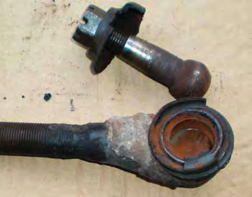
While his ride is a 1995 Ford F-150 truck, the problem he encountered could occur with virtually any vehicle. As it turned out, his left outer tie rod end broke apart. In other words, the joint had worn to such a degree that the “ball” pulled out of its socket.
Franz is a cabinetmaker by trade and his interest is in woodworking not cars or trucks, so he relies on people who service his vehicle to spot problems in the making. Furthermore, this vehicle is a fairly new addition to his family so he had no “gauge” to go by regarding the feel of the steering, at least not until it wouldn’t steer anymore.
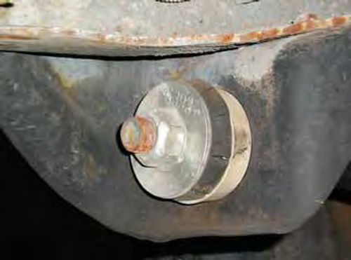
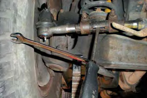
Photo #1 shows what I saw when I looked underneath the truck. The rust you see on the broken joint was certainly visible before it separated and is always an indication of impending failure.
Unfortunately, the guy or gal doing the servicing at the local “super fast we lube everything shop” may not take notice of these rather obvious signs, or just wasn’t feeling very motivated that day.
On the other hand, a do-it-yourself inspection is fairly easy, and in this case so is replacing the outer tie rod ends.
Plan for a Full Inspection
It’s easiest to start with a complete inspection to determine what will be needed for the repair. This way, we can try and make only one trip to the parts store.
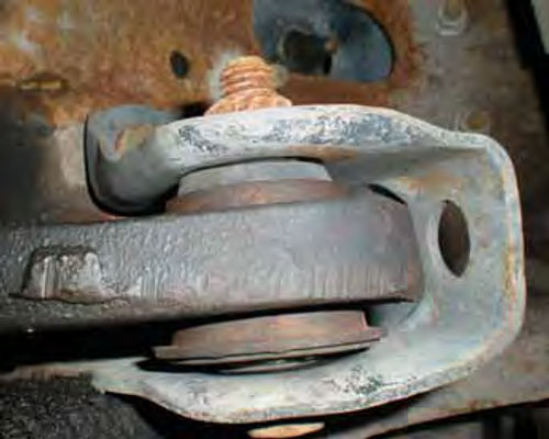
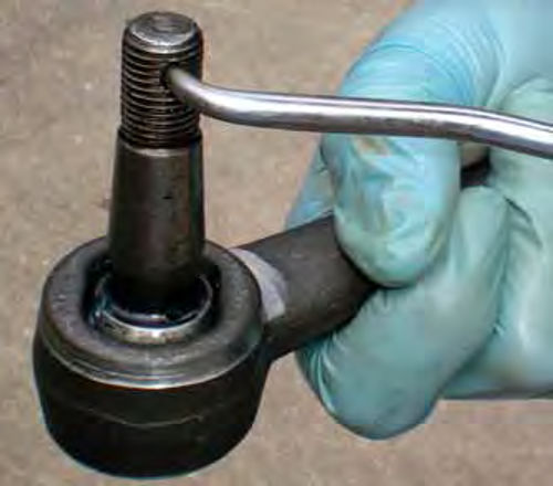
As previously mentioned, you should be looking for the presence of rust. Now I’m not talking about simple surface rust; that’s a given. Look for rust in and around the area of the joint’s rubber boot. Photo #2 is a close-up view of the broken tie rod end once it was removed. The boot was cracked and split and surrounded by fresh-looking rust. This is what you should be looking for.
Tie rod ends and similar-style steering linkage connecting joints should show no signs of looseness and you should not be able to compress them with hand pressure. If you are able to view the steering linkage joints without raising the vehicle’s wheels off the ground, that’s to your advantage as it will add resistance during the inspection.
Have an assistant move the steering wheel back and forth slowly until some resistance is felt. While your assistant is doing so, look closely at each joint. You are looking for lost motion in the steering linkage.
Make sure you have enough light to see clearly or this visual inspection won’t tell you much. The joint and whatever it’s connected to should move together as if it were one unit. If you notice a wobble, looseness or independent movement in the joint, it needs replacing.
Next, it’s time to raise the vehicle to allow inspection of the ball joints and get a look at the radius arm bushings. Apply the parking brake and chock the rear wheels for safety.
If you’re uncertain of the correct locations to place the jack for lifting your vehicle, check the service manual, and never get underneath it unless it’s properly supported on jack stands. For inspecting the ball joints on this Ford F-150 pickup, proper placement of the jack stands is under the I-beam axle near the wheels.
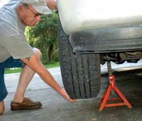
Photo 3 shows Franz getting involved by grabbing the tire at 12 o’clock and 6 o’clock and checking for looseness. Try this check again with your hands positioned opposite each other in several different locations. Also, a large bar or pipe can be placed underneath the raised tire to lift upward, and then flex it side to side. If any looseness is detected, have one person watch the ball joints.
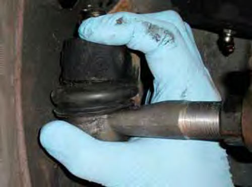
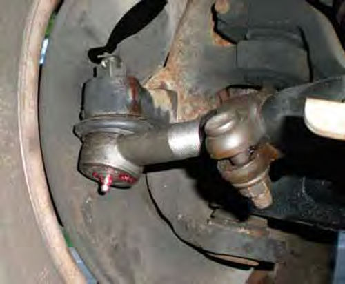
Photo 4 shows the upper ball joint (most commonly the one to wear out on this vehicle). Watch for any movement while your helper is supplying the muscle. Be looking in the area of its rubber boot for looseness. Inspect the lower ball joint in the same manner. About 1/32” movement is allowable for this vehicle’s ball joints. If some wobble is detected during this test, but the joints appear tight, it’s most likely due to looseness in the wheel bearings. These are easy to snug up and, as a matter of fact, a minor amount of end play (when cool) is required with many vehicles. This is to avoid a “preload” condition on the bearings once they become hot. Check your service manual for proper adjustment and lubrication service intervals. Then perform the same checks on the opposite wheel.
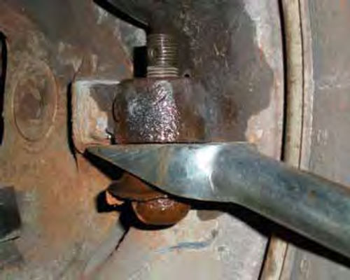
Now that there is room to get under the vehicle, let’s go back again to the tie rod ends for an additional check. Using the palm of your hand and fingers, grab the joint and the link it’s connected to and squeeze (Photo 5). If it can be compressed by hand, it should be replaced.
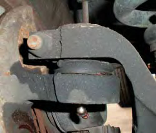
Always replace tie rod ends in pairs, either inner or outer. The same is true for ball joints; both upper and/or both lower. A look at Photo 6 shows the radius arm bushings have some pretty healthy cracks. Rubber bushings should all be inspected for peeling and cracking. These should be replaced, but as they don’t present any safety issues at this time, we will save that project for another day. Finally, Photo 7 is a look up at one of the I-beam bushings. The bushing and mounting bolt should all appear concentric. This one is in good shape, but don’t forget the other one. In general, if it’s something in the steering linkage or front suspension that “moves,” look at the “pivot area” for any wobble, looseness or cracked and peeling rubber.
A Tip: Keep in mind that there are several different front suspension styles and, in addition to being a safety measure, proper jack stand positioning is a must for a productive inspection. If the stands aren’t placed properly, you might be misled into thinking a ball joint is good when it’s actually in dire need of replacing.
Some manufacturers use ball joints with built-in wear indicators. Reference your shop manual for this information as well as proper lifting points.
If you don’t have a manual, don’t wait any longer to add one to your automotive library. A manual is not that expensive and it will become one of your most-used tools.
As it turned out, once we completed our in-depth inspection, our parts list for this project wound up being two outer tie rod ends.
Time to Replace the Tie Rod Ends
First use a wire brush and knock off any dirt and grease build-up. Spray penetrating oil inside the tie rod sleeve as well as on any nuts or bolts that will require loosening.
Next, loosen only the sleeve clamp closest to the tie rod end that’s being replaced. Both of the outer tie rod ends are being replaced, so it is safe to use a “pickle” fork for separating as shown in Photo 8.
If you were removing any tie rod end (or ball joint for that matter) with the intent of reusing the joint, don’t use a fork as it will damage the boot. Instead, use a puller made for the purpose. Another option is to strike the joint connection with a strong blow from a hammer. That would be the part of the spindle you see above the fork in Photo #8. (Don’t hammer on the ball stud itself). You will need to have enough room to swing a hammer or can use the aid of a long blunt object and strike it. This may sound somewhat primitive but it works and is an accepted method to free joints. In this case, one strike of the hammer was all it took and the ball stud was removed from the spindle connection.
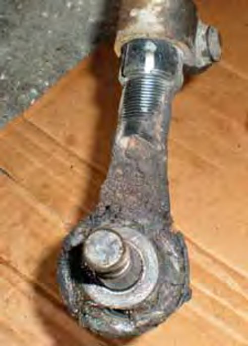
Finally, it’s time to thread out the old tie rod end. First make a reference mark between the sleeve and tie rod end as seen in Photo 9.
You will be counting the number of turns required to remove it, and these marks will help keep track. Paying attention at this point will save you time in the long run.
Initially, I count full turns until it starts to feel loose, then I start thinking in terms of half turns. The left tie rod end took thirty and one quarter turns to remove it. To verify if that last partial turn was a quarter, half or somewhere in-between, I will thread it back into the sleeve to see where the threads pick up.
If you are having difficulty in rotating the old tie rod end, consider inserting something into the sleeve to spread it open. Photo 10 is an example of this procedure. Insert a screwdriver with a wrench on its shaft for added leverage to spread the sleeve. In a larger opening, a chisel possibly will do. If you live in the North, you are likely fighting with a lot of rust that’s bonding the pieces together. This method, in combination with penetrating oil, will eventually free it. While I have never had to resort to it, heating the sleeve with an oxy-acetylene torch would certainly free it in the worst-case scenario. Should this method be used, be aware of your surroundings while working for safety purposes.
Also, if the sleeve is severely rusted, check with your local parts store for the availability of replacements.
A Few More Installation Tips
It’s time to thread in the new joint, but first take some time to make sure the orientation of the cotter pin hole is conveniently located so it’s easy to pull the cotter pin through.
The new joint will be stiff, so use something like the pick tool shown in Photo 11 to rotate it. Of course, not all joints use cotter pins to secure them.
Once you start threading the new end into the sleeve, note where the threads picked up and count the revolutions. Don’t be surprised if the new end starts at a different location than the old one did. Just get the thread count as close as possible, making sure the spindle hole is free of debris and insert the ball stud into it. It’s very possible that it won’t line up with the hole. Sometimes you can change the angle of the stud using a rag and the palm of your hand. These tie rod ends, however, were too tight to do that so I installed the nut onto the ball stud and then placed a socket with an extension on it for leverage. Once connected to the spindle, torque down the nut. Specifications show 70-100 ft.-lb. of torque for our vehicle. Somewhere within that range line up the cotter pin hole with the castle nut and pin it. Repeat the same procedure with the opposite side.
Now, the chances of the toe-in adjustment being correct are less than zero, which means we will be adjusting one or both tie rod sleeves to correct it. To be safe, tighten up both sleeve clamps, but make sure all the tie rod ends are centered first.
A look at Photo #12 shows the right tie rod end is off center now that the truck is sitting on the ground. If this happens, loosen the clamp and re-center it. If you don’t, leaving it in such a position could result in binding and premature wear.
Next, we’ll set the vehicle’s toe-in and center the steering wheel.


