How -to Let’s Avoid Steering Failure, Pt. 2
Last Month We Made Repairs to a Pickup’s Steering Linkage. Now We’ll Check Toe-In With a Gauge…and String.
LAST MONTH WE went over the steering linkage of a Ford F-150 pickup looking for potential problems and took care of a very obvious problem by replacing a broken tie rod end. In this installment, we’ll wrap up our front-end project by checking the toe-in and steering wheel alignment. There were a DOZEN photos with the first installment, so we’ll start here with Photo 13.
Setting the Toe-In Adjustment
Any time you replace any components in the steering linkage, the toe-in portion of the alignment needs to be rechecked. Certain tire wear patterns will also indicate the need for toe adjustment. A feathered edge toward the inside of the tires is usually indicative of too much toe-in (the tire is pointing too far inward as seen from the front of the vehicle), while feathering toward the outside would indicate a toe-out condition.
If you choose not to do this yourself, then the only task that remains is to lube the new front-end components and drive to your local alignment shop.
If, however, you enjoy doing as much work as you can on your vehicle, then the final steps in the steering project are the toe-in adjustment and making sure the steering wheel is centered. I will show two methods for performing these tasks.
Working With an Alignment Gauge
Photo #13 shows the gauge portion of a toe-in adjustment tool. The gauge is spring-loaded and rides against the sidewall of the tire. At the opposite end is a piece of flat stock aluminum that is bent at a 90° angle. This is positioned against the outer sidewall of the other tire. The maximum working range of this tool is about 81 inches. This one was purchased from The Eastwood Company years ago, and it’s also available through JC Whitney which sells it as the Manco wheel alignment gauge ($50).
To get started, have the vehicle on a somewhat level paved surface with enough of a runway that allows you to back up, and then roll straight forward, say, eight to 10 feet. Bring the vehicle to a stop without using the brake pedal or touching the steering wheel. If you’re a good judge of distance, you can coast to a stop, but the parking brake is probably the safest thing to use.
Once stopped, apply the parking brake and shut off the vehicle as you normally would. Now you are ready to take a reading. Place the gauge behind the front tires with the fixed end up against the outer sidewall of the right tire. Loosen and slide the gauge end until it is resting on the outside sidewall of the left tire. Verify that the support foot of the tool is sitting level and then zero the gauge and tighten the thumb screw to secure it in that position. Carefully remove the tool from behind the wheels and reposition it up front in the same manner. This time, the gauge will be up against the sidewall of the right tire; note the reading. Most vehicles require around 1/16” to 1/8” toe-in, but this is a very general statement, so check your manual.
There are two things you’re going for here, the correct amount of toe-in and having the steering wheel centered. Note that there are some older vehicles (1950s and earlier) where the steering wheel is centered by making an adjustment in the drag link. On others you may not be able to center the steering wheel when correcting the toe adjustment. I had a mid-’60s GMC Value Van (a typical “Bread” truck) that was that way. It had one long tie rod sleeve for adjusting. Once the setting was correct, that was it. If the steering wheel was off center you lived with it or removed and repositioned the wheel.

Well, back to the Ford F-150. Our first reading was 3/16” toe-out, not too bad considering where we had come from. But what about the position of the steering wheel? There are a couple of ways to approach it. If you are in a rural area with some straight roadways close by, take it for a road test and note the location of the steering wheel spokes. That’s the method I chose this time and I found the central spoke of the steering wheel to be at 2 o’clock and 8 o’clock, as if making a slight left turn. To determine which sleeves need to be adjusted, “listen” carefully and visualize the following. Hold your hands about 6”- 12” apart and think of them as both the right and left front wheels respectively.
The steering wheel’s position with relationship to your hands:
A. Steering wheel turned to the right as if making a right turn = your fingers pointing to the right. To what degree is not important.
B. Steering wheel turned to the left = fingers pointing to the left.
C. Steering wheel straight ahead & centered = fingers point straight.
Next, using your hands indicate the toe-in or out condition:
1. Toe-in = fingers on both hands would be pointing inward slightly. (How much is not important.)
2. Toe-out = fingers pointing outward slightly on both hands.
3. Zero = hands and fingers straight ahead, parallel.
The Ford F-150 is running toe-out and the steering wheel isn’t straight. Remember the spokes were at 2 o’clock and 8 o’clock and we want them to be at 3 o’clock and 9 o’clock, so the steering wheel will have to be rotated to the right to correct this.
Duplicating this condition with your hands—fingers on both hands pointing outward, away from each other. This mimics the toe-out condition. Now turn your hands to the right. This simulates theaction taken when rotating the steering wheel to the right to get it straight. Without moving your hands,think about this situation. The steering wheel is straight, and the vehicle is running toe-out. This hand simulation indicates that the right wheel is toe-out. Loosen both clamps on the right tie rod sleeve, then rotate it to adjust the wheel inward. This is correcting the toe-out condition and centering the steering wheel.
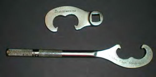
There are special tools for rotating the tie rod sleeves and two variations are shown in Photo #14, although slip joint pliers usually will do the job. Just try to avoid squeezing too much on the sleeve as this will make it more difficult to turn.
Use the toe-in gauge to do a quick check of the adjustment. The Ford was now set at 1/8” toe-in, so I made sure the tie rod ends were centered properly and the sleeve clamps were tightened.
Once again it was time for a road test. The steering wheel was close to being centered, but not quite there. It was still as if it was making the slightest left turn.
Returning back to the work area, I coasted the vehicle straight in, using the parking brake to stop.
In re-checking the toe adjustment, it now indicated 1/16” toe-in, a bit less than I had wanted. The adjustment would again be made on the right side in an effort to center the steering wheel, and it wouldn’t be very much. Again, a quick check was made with the gauge and it read 1/8”. This time the road test showed the steering wheel to be straight, and if the adjustment was still correct, the job was done.
I coasted in and re-checked the adjustment. It was now 3/32” toe-in, slightly less than what I was targeting, but within tolerance limits.
Several additional road tests and gauge checks were made and all looked consistent from there on.

Why did the reading change? First, by not coasting in after making the final adjustment, we didn’t get the normal spreading outward of the tires, so that could have affected the reading. That’s why I called it a “quick check.” Secondly, the gauge itself doesn’t take in to account tire and/or wheel run out. That is why I drove and rechecked the adjustment several times. The fact that the Ford has aluminum wheels is a big plus in this regard. Aluminum wheels run much truer than steel. The tires themselves also have a certain amount of run out. If you have a smooth sidewall tire, the gaugecan be used to check run out and locate the high spot. Elevate either tire so that it is just off the ground and can spin freely. Position the gauge up against the elevated tire, and the fixed loop end around the other tire. Zero the gauge, now slowly rotate the tire. The needle on the gauge will indicate high and low spots. Don’t be mislead by things like tire mold lines that may give a sudden drop in the reading. Once the high spot is located, mark it and position it at 12 o’clock and lower the wheel. Do the same procedure with the other tire.
Now back straight up and roll forward as we did before when making our checks and stop (using the parking brake) with the high spots at 12 o’clock. Now check the reading. This is the most accurate reading you can achieve with this type of gauge. Unfortunately, the Ford F-150 has raised letter tires,so this was not possible.
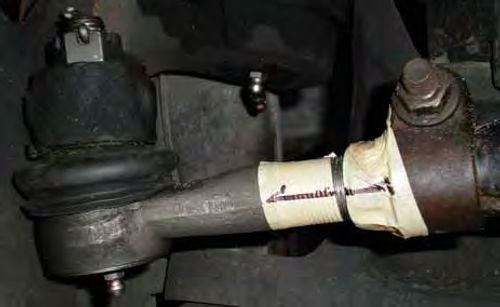
Hand simulation will direct you to which tire will need the primary attention, but it won’t tell you how much adjustment to make. With the F-150 all the adjustment was made on the right side. It was possible that when I road tested it after the first adjustment the steering wheel could have been off center in the opposite direction. Making all the adjustment on one side could have been too much. Had that happened and the setting was correct at 1/8” go back to the hand simulation again. Hands toe-in, and this time turning left to correct the steering wheel’s position. Now the steering wheel is straight, but your hands (tires) aren’t. Move your right hand(tire) toe-out, and your left hand (tire)toe-in. Both sides will need to be moved equal amounts in order to maintain the correct adjustment. Wrap a section of masking tape around each tie rod end about 1/4” from where it threads into the sleeve. Also wrap a piece around the end of each sleeve. The end result should resemble photo #15. This gives a clearly defined surface you can mark up using a Sharpie, and will make it much easier to make equal adjustments to both sides.
Now, a few more examples of the “hands are wheels simulation.”
1. If our vehicle had been toe-in too much with the steering wheel located at 2 o’clock& 8 o’clock= the left tire would be adjusted outward as the primary adjustment.
2. Toe-in too much, but the steering wheel is properly centered = adjust both wheels outward equal amounts.
3. Toe-out too much, and the steering wheel is properly centered = adjust both wheels inward equal amounts.
4. Toe-in adjustment reading is correct, but the steering wheel isn’t centered = depending on which way the wheel is turning, the adjustments will be of equal amounts, but in opposite directions.
A Tip: When turning the tie rod sleeves to make adjustments, make a note with regard to which way you rotate it, and what it does. Something like this: “Right side—rotating the tie rod sleeve the same direction as for ward tire rotation decreases toe-in (or moves the front of the tire outward).” It’s easy to forget what direction you were rotating the sleeve, so simple notes can help avoid complicating things.
One final thought before moving on. Had the initial gauge reading been extremely far off, some adjustment would be necessary before road testing; otherwise you might literally be dragging and scuffing the tires down the road. If you have a long enough straight drive way, try and judge the position of the steering wheel and use the hand simulation method to judge where to make adjustments. If that’s not an option, make equal adjustments to both sides until the setting is close enough. This will keep the steering wheel at its current position. That may be good, or not, but once on the road you will be able to apply your hand simulation knowledge if it’s off center.
An Alternative Method for Centering the Steering Wheel
A second way to achieve a straight steering wheel is to use string as a guide. This method usually eliminates some of the road testing, but that doesn’t mean it’s faster. Also, it is only effective for vehicles where the front and rear wheels are tracking close to the same. If you are running big fat tires in back and narrow ones up front, stick with the first method outlined above.
You will need two lengths of thin (kite- flying) string. They must be long enough to attach to the back of the rear tire and extend up to about the front bumper.
Start by establishing a gauge reading just as before. Next, center the steering wheel. Have the parking brake applied for all these procedures. Rock the steering wheel back and forth gradually, coming to stop on center. If the vehicle has power steering, start the engine and, under power assist, rotate the steering wheel and gradually locate center.
Without disturbing anything, turn off the engine and lock the steering wheel in this position. Photo #16 shows a steering wheel lock made specifically for alignment work. It was purchased at a local swap meet for $10. You could also make one fairly easily from wood. For your reference, this tool is 12” high, and the spring-loaded section that grips the wheel is 6” wide.
Attach a string to each rear tire. Try making a bulky knot at the end of the string and wedge it into the tire tread. If that’s not possible, use a section of duct tape to hold it there.
You want to place the string as high as possible, but it can’t touch the vehicle’s body when it is pulled straight forward. If wheel covers interfere, remove them. In some cases you may need to remove those small front mud flaps some vehicles have.
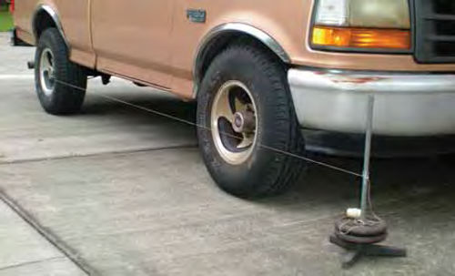
Pulling the string snug, have it touch the sidewall of the rear tire, and see where it makes contact with the front tire. Photo #17 is what this process will look like. In the photo, the string is attached up front to an old weighted- down microphone stand, but it could simply be held by hand.
If your toe-in is correct and the steering wheel properly centered, you should have the string contact the rear edge of both front tires and have the slightest air gap at the front of each sidewall as we see in Photo #18. This gap between the string and the sidewall shows that you have toe-in on both wheels, and it should be equal. Had the string contacted the front sidewall and not the rear, that indicates toe-out, and the air gap is an “indication” of how much. These strings on each side of the vehicle will show whether both tires require adjusting or only one.
Use the gauge to make quick checks to see where the adjustment is going. Note where the air gaps are to determine if a tire needs adjusting, and what direction it needs to go. When you believe it’s right, tighten down any clamps that were loosened, making sure the tie rod ends are centered up as mentioned in last month’s installment.
With the steering wheel lock still in position, push outward on the forward edges of both front tires. Assuming you are most likely lying on the ground in front of the vehicle doing this, use a foot to push on one tire and your hands to push the other. The idea is to make sure the tires are spread outward as much as possible.
Now take another toe-in reading. If it indicates additional adjustment is needed, do so. If OK, remove the string and take the vehicle for a test drive and note the steering wheel’s position.
Return to your work area and coast in for the final check. If the steering wheel is straight and the reading correct, you’re done. But don’t be surprised if you still need to make minor corrections. This is a time-consuming process to make sure it is right.
For your reference, the tools used to perform the repair and adjustments in this two-part series were: A rolling floor jack, jack stands, wheel chocks, separating (pickle) fork, tie rod sleeve adjusting tool, toe-in gauge, steering wheel lock, pick tool, masking tape, Sharpie and kite-flying string. Of course, a selection of basic hand tools and penetrating oil are needed as well.
So, use your hands or get out the kite string and “get it done!”
Resources Eastwood Co.
JC Whitney