If You See the “Check Engine” Light, Pt. 1
When That Warning Light Glows, You Need to Find the Cause. This Four-Part Series Will Help Your Detective Work.
DOES YOUR VEHICLE’S “check engine” light come on as you’re driving down the highway?
You “give it the gas” and it stays on? You let up on it and it stays on? Then you stop at the market, let your car sit for 30 minutes, and as you drive home, the “check engine” light stays off! Wow! Whew! “No more problems.”
Monday, you drive to work and the check engine light comes on again! “I wonder what it is? These darn modern computers. I wish I had points again in the distributor.”
During this time, you may also notice some drivability symptoms (like hesitation on takeoff), reduced gas mileage, and/or barely passing the last smog check inspection.
There may or may not be any quick answers regarding this scenario.
So, a good approach to this project is to first establish some history of the “check engine” light being on and the symptoms of poor performance.
Then we’ll do a tune-up prior to checking for trouble codes in our search for the reason or reasons why the “check engine” light is coming on.
The Importance of a Tune-Up
On our ’95 Mercury with a 3.8-liter fuel-injected engine and 85,000 miles on the odometer, let’s check the vehicle’s tune-up status. Quite often, the need for a minor tune-up or lack of a maintenance item may cause the “check engine” light to come on.
Start your tune-up by checking the cranking and charging voltage. The cranking voltage must be at least 10 volts or more. The charging voltage must be at least 14 volts.
On our Mercury, the cranking voltage measured 10.8 and the charging voltage measured 14.3 with the lights and AC on. All’s OK
Both tests confirmed the cranking and charging systems are OK.
My Web site, milttheinstructor.com, includes a how-to article on measuring these voltages at the battery.
Spark Plugs: Check the vehicle’s spark plugs and analyze the inner porcelain. It should be white on a computer controlled vehicle.
If it’s tan, there may be minor fuel mixture problems.
If the plug inner porcelain is dark orange, black or oily, you may have major tune-up, fuel mixture or engine problems (oil burning?).
On our Mercury, two plugs were removed for inspection. The porcelains were white with a very light brown spot and a very minor buildup on the ground electrode.
The plug gaps checked out at 0.053 inch. The under hood label specification is 0.052 to 0.056 inch.
Next, perform a plug firing voltage check. Attach a kilovolt (KV) tester to the #1 plug wire and measure the KV at idle. Then momentarily tromp on the gas up to around 2000 rpm to measure the plug voltage under engine load.
On our Mercury the plug firing voltage was 15 to 20 kilovolts at idle, increasing up to 25 KV when tromping on the gas pedal. The KVs were measured on all six plug wires.
“Tromping on the gas” momentarily is opening the throttle quickly to wide open (WOT), and watching the plug firing voltage increase.
Bear in mind the plug KV test is performed at a light engine load. Sustained wide-open throttle operation while driving on the road may result in bucking (ignition misfire).
Plug Wire Check: If you measure a continuous KV of 50 kilovolts or more on a plug wire you have an “open” secondary circuit. Test all the plug wires.
If the plug wires are five years old or older, replace the whole set.
Coil Checks: The “open circuit” voltage was 51 KV indicating the coil system was producing adequate “reserve” voltage all the way to the spark plugs.
All the above tests proved the ignition system was “sparking” and there was no ignition misfire.
Base Timing: The base timing was checked at idle with the “spout” (spark output) disconnected. It measured 10 degrees BTC, right on the spec. The specification and procedure is located on the underhood emission label.
If the label is gone, look up the timing spec and procedures in performance tune-up manuals. (Visit motor.com. They may be able to help with these tune-up manuals).
The base timing (if adjustable) must be at spec. The computer will not compensate for mis-adjustment.
Air Inlet Boot: The air inlet boot for the MAF (mass air flow) sensor had no air leaks.
As you remove the inlet boot turn it upside-down and inspect it for cracks.
The inside of our Mercury air inlet boot had an “oily looking liquid,” most likely entering into the induction system from the PCV system vent. My guess is the liquid we discovered is condensed blowby from the crankcase.
Remember the ’92 Ford 4.6-liter FI truck article published in the October 2008 Auto Restorer? That inlet air boot was full of holes on the bottom side allowing “false” air to enter into the induction system, bypassing the MAF sensor input to the computer. A No No!
Throttle Body: Clean the throttle body around the throttle plate using paint thinner and a rag on a screwdriver. Open the throttle and wipe out the “gum” where the blade closes in the throttle bore.
On our Mercury engine, the throttle body was clean!
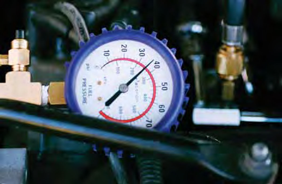
Fuel Pressure: Attach a fuel pressure gauge to the 1/8 Schrader (Ford) fuel rail fitting. Turn the key on and measure the pressure. Start the engine and measure the pressure again. Compare your results to the specs outlined in Performance Tuneup Manuals, (again, check motor.com). All data references also provide tune-up specifications.
Our Mercury measured 38 PSI key on, engine off. It measured 30 PSI at idle and 38 PSI when “tromping” on the gas. (See Photo 1.)
Measured fuel flow was 200 milliliters (200 cc) in 10 seconds, using a Sears pressure tester.
These results are all within the specifications. All of this proved the fuel system pressures and fuel flow were OK and should not be contributing to our check engine light symptom.
The fuel filter was changed for maintenance. It had not been changed in 25,000 miles.
Vacuum Lines: This is a good time to check all the vacuum lines for cracks or “mushiness” Also, review the under hood vacuum line diagram to ensure the routings are correct.
Emission Controls: Test the PCV and the EGR System
As discussed above, we found oil residue inside the air inlet tube.
Clean the PCV valve with carburetor cleaner. With the engine off, lift the PCV valve out of the rocker arm cover and spray carb cleaner into the PCV valve inlet. Let it soak while performing other tune-up checks.
After cleaning, start the engine to suck in the cleaner, then re-install the PCV into the rocker arm cover.
After this cleaning procedure, you can do a quick system check at idle by plugging off the PCV vent hose with your thumb for several seconds.
After five seconds, lift your thumb off the PCV vent. You should feel a rush of air sucking inward. This proves the PCV system is working.
Now disconnect the EGR vacuum line. Test the EGR valve with a hand vacuum pump. Pump up the vacuum to around 5 inches. The engine should stumble violently. Release the vacuum; the engine should return to a smooth idle.
Next, attach a vacuum gauge to the EGR valve signal line. Rev up in Neutral to around 2500 rpm and hold it steady.
Usually, the EGR signal vacuum will increase from 0 at idle up to 2” at 2500 rpm, then “flicker” and drop back to zero within 2-5 seconds.
The engine computer is turning off the EGR signal vacuum at the EGR solenoid because the vehicle is not moving. There’s no need for EGR at idle or at 2500 rpm in Neutral.
If it doesn’t show a signal at 2500, drive the vehicle on the road at 30 mph and test the EGR signal vacuum. On the road, many EGR system signal vacuums will measure from 1 to 5 inches of Mercury. There are no specs available. When testing just make sure there is a signal vacuum. The EGR valve operation and the signal vacuum is your functional test.
Idle Control: Test the idle air bypass function. Start the engine and note the initial rpm in Park, it should “zoom up” to around 1500 rpm at startup, and then drop off to around 800 in Park within 5 seconds from start on a previously warmed-up engine.
Put the transmission in drive and read the rpm. Then turn on the air conditioning. The idle should “hold” at around the same rpm. This test proves the IAB (idle air bypass) solenoid is working normally.
Our test vehicle (’95 Mercury) measured around 800 in Park, 750 in Drive and it would “hold” at 750 rpm when turning on the air conditioning. These readings are all normal.
Computer Checks
By now you no doubt can see why you need to perform a tune-up before diagnosing the check engine light problem. Obviously, the tune-up items listed above must be correct before you can move on with your testing.
For example, if one plug misfires “occasionally,” lots of oxygen-and-fuel mix in the misfiring cylinder is left over and is pumped right into the exhaust stream unburned. This temporarily “fools” the computer through the oxygen sensor signal. The computer thinks the mixture is very lean because there is lots of oxygen left over from the misfiring cylinder.
At this “lean” point the oxygen sensor voltage is very low (0.2 volts or less) and may not be “switching.” The computer responds with a “rich correction” (a very slight increase in injector “pulse width”).
In this scenario, an oxygen sensor code may be falsely triggered because of an occasional spark plug misfire.
So, it’s very prudent to get the tune-up correct first; then proceed with a search for check engine light causes.
OBDI AND II: Most ’95 year vehicles are OBDI (On Board Diagnostic, phase I).
Some of these ’95 model OBDI systems may be equipped with a standardized 17-pin OBD II diagnostic connector.
OBDI systems do not have “misfire monitors” like the OBDII systems. (For example, ’96 3.8-liter Ford engines are OBDII.)
Diagnostic Trouble Codes: Our next shot is to read the “codes.” Our Mercury vehicle had a 171 stored code entitled “bank 1, lean mixture, EGO not switching.”
In English, this means the transverse engine back bank oxygen sensor for cylinders 1, 2 and 3 was not switching from 0.2 to 0.8 volts for a short time resulting in the check engine light coming on and setting trouble code 171.
When the check engine light goes out, the O2 sensor was probably starting to switch again. Then down the road the O2 sensor stops switching. Again, the check engine light comes on.
The ’95 Mercury has 85,000 miles in 13 years. The O2 sensors are old, with lots of short miles. In this scenario, the oxygen sensor may just have become “lazy.”
(Part 3 of this series will discuss more details on oxygen sensor wave forms, outlining misfire, “lazy” and “dead” O2 sensors.)
Fuel Injector Cleaning
The injectors were cleaned through the fuel rail 1/8 Schrader fitting.
Disconnect the fuel pump at the pump connector or remove the “fuel pump fuse.”
Look up the fuse locations in your vehicle owners manual.
All Ford fuel-injected engines have a fuel pump safety disconnect switch. It shuts off the fuel pump during the sharp impacts of vehicle accidents.
For fuel injector cleaning, “bump” the shutoff switch and let the engine die while losing fuel pressure.
Hook up the injector cleaning equipment and install the cleaner in accordance with the injector equipment manufacturer’s instructions.
Most injector cleaner products contain cleaner and fuel. Some products require gasoline mix with the cleaner.
Adjust the equipment pressure to 5 PSI below the engine fuel pressure, so the cleaner will not return to the tank through the fuel return line.
On our Mercury we adjusted the equipment pressure to 25 PSI, started the engine, ran it for 10 minutes, turned it off, disconnected the equipment, and re-connected the pump.
Safety Check: After removing the injector equipment, turn on the key twice to build pressure. Inspect the fuel system to verify there are no fuel leaks. Start the engine and run it until it “smooths out.” Recheck the fuel lines for leaks.
You can purchase FI cleaning kits through NAPA, Car Quest Auto Parts stores or automotive equipment catalogs.
I use a BG Products cleaning unit, model 9210 Inject-A-Flush FI Apparatus, which is pressurized with shop air, and BG fuel injector cleaner kits. (BG Products, Inc. is located in Wichita, Kansas; bgprod.com).
An alternative method for injector cleaning is to use an injector cleaner (like Lucas) in your fuel tank as instructed by the FI cleaner manufacturer.
This method takes longer (in miles) to clean the injectors than when using a fuel injector direct rail kit. Putting injector cleaner directly into the fuel rail results in instant driveability improvement.
These fuel tank injector cleaning liquids generally are available at local auto parts stores.
Take a Test Run
Record the diagnostic trouble codes then “clear” them.
Test run your vehicle to evaluate your tune-up. Does it start quickly (less than two seconds) after beginning the cranking with your foot off the gas?
Does it run smoothly with no hesitation? Does the check engine light come on? When?
Now, what if the check engine light still comes on and the code sets? Check the codes again and test the oxygen sensor as outlined here:
Oxygen Sensor Tests, On Car, Generic
1. You did your tune-up first.
2. Equipment Hookup.
• Back probe, with a “T” head pin, O2 at the connector. (+) lead to O2 wire, (-) lead to ground at battery negative terminal.
Note: When measuring low voltages on computer-controlled vehicles, use digital volt-ohm meters, only. Digital meters will not affect the current or voltage measurements. Analog (needle) type voltohmmeter measurements will affect current and voltage measurements, producing inaccurate results.
3. Confirm Closed Loop
• Run engine more than two minutes at 2500 rpm to normalize the operating temperatures.
• Run the engine at idle.
• Verify downstream air injection to converter, if the vehicle is so equipped. Feel pulses in the air injection hose downstream of the oxygen sensor.
• Measure oxygen sensor voltage at idle and 2500 rpm.
4. Results
• Closed loop: Voltage should vary from 0.2-0.8 volt within two seconds on most carbureted engines and within one second on most fuel-injected engines.
• Rich mixture: Volts fixed at 0.8 volt (800 millivolts). Sometimes it may be fixed at a lower voltage like 0.6 or 0.4.
• Lean mixture: Volts fixed at 0.2 volt (200 millivolts).
• Open loop: Volts may be fixed, with readings at 0 or 0.4.
5. Are the Computer and Oxygen sensor Working?
• Momentarily squirt carburetor cleaner into an intake manifold vacuum port. The oxygen sensor voltage should increase rapidly up to 0.8.
• Lean the mixture: oxygen sensor voltage should decrease to zero.
• If the O2 voltage is pegged at 0.8 volts or more, the mixture may be rich. Disconnect a vacuum line or the PCV hose. Pinch the hose, allowing a small leak to lean the mixture. Increase the vacuum leak until you see the oxygen sensor voltage varying from 0.2-0.8 volts.
• Confirm O2 sensor is switching voltage within two seconds.
• If O2 is not switching, check fuses and grounds.
• Correct lean or rich mixture symptoms (tune-up, fuel mixture).
• If not switching, diagnose for lazy oxygen sensor.
• Refer to computer control trouble charts, even if there are no codes.
Note: Part 4 of this series, “Closed Loop Review,” outlines more details on how to confirm closed loop and tests for lean or rich mixtures and lazy or dead oxygen sensors.


Part 2 of this series will discuss “scanner” engine tune-up data.


