
Dealing With Rust
Project Vehicles Generally Have At Least One Thing In Common—Rust. So Let’s Ask a Restoration Pro How He Approaches This Widespread Problem.
WE ENCOUNTER SOME type of rust out on virtually every project we build and it needs to be dealt with effectively in order to remove it forever. Furthermore, there are many different areas that rust on a car or truck’s body and they require different techniques to remove them. So let’s take a look at some effective approaches to rust removal.
Photo 1. Before we get started on rust repairs, it’s important to go over some of the tools needed, especially in the areas of welding and grinding the welds down smoothly and efficiently. Starting with the welder, this Miller 135 is a great machine for performance and durability and it will weld from thin 22 gauge to penetrating 3 ⁄16th-thick metal which is plenty for any project you may be building.
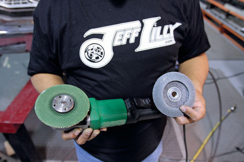
Photo 2. Grinding is a very important step and here are some proven tools that get it done right. The 4-inch 10,000 rpm grinder on the left works well to “rough” out welds on high crown areas that are easy to get to. This one is a Bosch but DeWalt and Makita are also good choices. The green Cubitron disc lasts very long and is 3M’s latest technology. To the right is a flap wheel which is used on the same tool to finish off the metal very smoothly. No compressor is needed with electric tools.
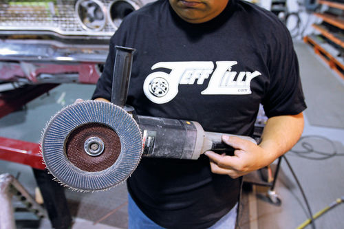
Photo 3. This is a Porter Cable variable-speed buffer/sander tool that we use for grinding. There are many manufacturers of this type of tool including Makita, Black+Decker, etc. They will turn 200 to 4000 rpm depending on the settings and how much you depress the electronic switch. We use it with a 10-inch flap wheel from Norton. Because of the surface feet per minute covered by the large diameter wheel, it removes material fast, leaves a nice finish and does not heat up the metal like a smaller wheel does. No air compressor is needed with this electric tool.
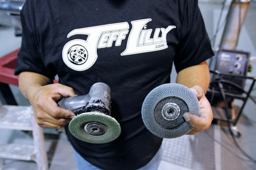
Photo 4. If you feel more comfortable using smaller tools, then the same Cubitron disc can go on this air-powered “large angle grinder” on the left for a little more control with the same flap wheel. You need a minimum 5 horsepower or 8-10 cubic feet per minute compressor to operate it.
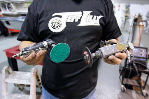
Photo 5. This is the most commonly used set of tools for this type of project. They are lightweight and low cost. They are slower at removing material but also safer. With their smaller size they also can get in to tighter areas. Rated at 10,000 rpm, these are available from many manufacturers. The common small angle grinder or die grinder as some call it on the left along with the cutoff tool using a 1 ⁄8 th-thick wheel. The cutoff grinder is used to work the welds down to a very close level, then the Roloc disc on the angle grinder takes the welds down to a finish base metal level.
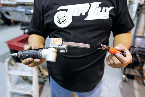
Photo 6. For hard-to-reach areas, a belt grinder is a good choice and the MIG tip cleaner keeps the welder performing at its peak.
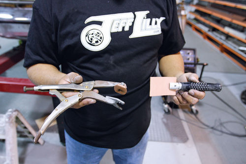
Photo 7. The copper spoon on the right works great to hold against the back side of pinholes to keep the welding wire from pushing past the panel and retains a flush weld. The copper pad clamp works well when you have holes close to an edge.
Photo 8. Luie holds the cutoff grinder at the correct angle to achieve the best results. This allows a good sightline and helps keep you directly on top of the weld and not dropping off the edge and hitting the base metal. In addition, notice how he holds his hands like a tripod against the panel. This stabilizes the tool and allows more precise grinding.
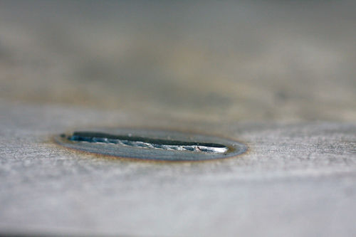
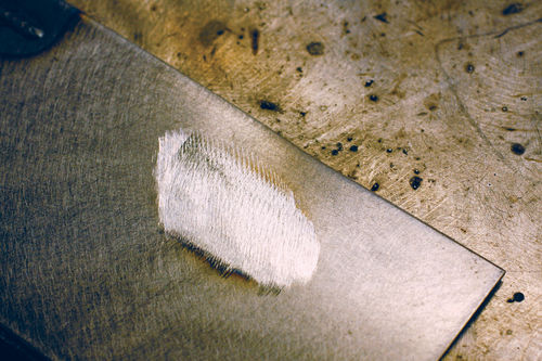
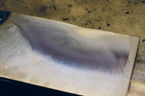
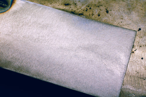

Photo 9. This is what you are after with your grinding — no base metal touched, only the weld.
Photo 10. This side angle shows when it is time to use the finish grinder such as the small angle grinder with a Roloc disc shown in Photo 5.
Photo 11. Once it gets down to this level, it’s time to use a DA or dual action sander with 80-grit sandpaper on the grinder mode.
Photo 12. The DA in grind mode using 80-grit sandpaper finishes it to this state.
Photo 13. The orbital mode of the DA shows a perfect finish. No base metal was touched beyond the factory 20-gauge thickness.
It’s Time to Start Repairing Some Rust
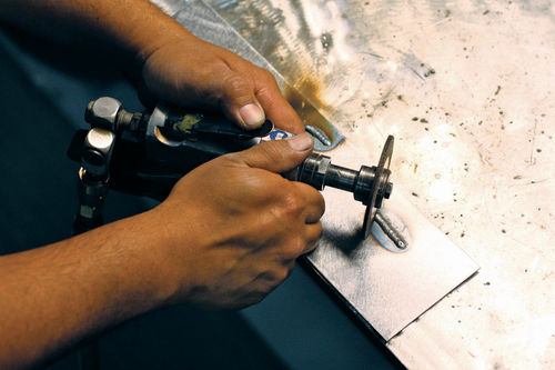
Photo 14. We’ll start off with the typical pinhole. These usually will not show up until all the paint is removed and media blasting takes place. They are easier to repair than replacing a whole panel especially when full access from behind a panel is available. Spot touching them with a MIG or TIG welder is the best solution. If you are good with Oxy and Acetylene then sweating a few drops of brass to fill them is also a good choice.
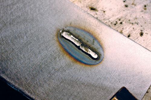
Photo 15. If needed, you can use “copper” in various shapes flat, round, angles, etc. that fit your panel where you need to spot weld. This will keep the weld from pushing out on the back side. If you are good at welding simply spot tack around the hole and work your way in to fill it up. Becoming a good grinder of welds is the biggest challenge. The goal is to grind it smooth without hitting the base metal around it to take it flush.
Photo 16. The next common area is where exfoliation takes place because of water that gets trapped inside a panel and slowly seeps in and around a folded seam. This is a trunk lid edge which has rusted from condensation running from the top of the lid down onto the seam year after year resulting in what you see here. We media blasted to show what we truly have and we are ready to do battle. Doors and trunk lids are the most common panels with this problem. In order to keep from replacing the complete panel or outer skin, if there even is one available, this is a good solid repair technique and will save time which is money.
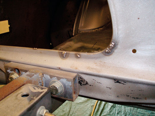
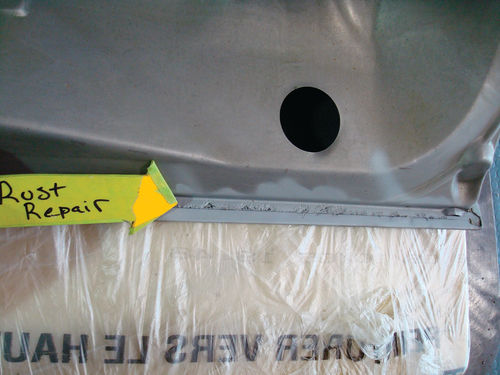
Photo 17. The first thing to do is drill out any spot welds and gently peel back the edge so you can get to the trouble areas. Use a strong putty knife or thin-bladed chisel to tap and lift or a similar tool can do the job. As seen, we then spot touched the holes and will now media blast the edge before folding it back.
Photo 18. Using a block of wood on the outer skin we can slowly hammer tap the edge back over or use pliers to squeeze it back tight. We then weld it back up.
Photo 19. A few tools that we use to accomplish these tasks are simple flat pliers, sheet metal roofer seam pliers and other peel-back tools.
Photo 20. Like any project, stripping the paint off is the first step as things are not always as they seem. Here we see old plastic filler that a shop used to fill in the rust.
Photo 21. After all the filler was removed you can see they never cut out the rust but simply floated it with good old plastic.
Photo 22. Always make a template that will go past the rusted section a minimum of a 1 ⁄2-inch so that you have full thickness of the original metal to weld on.
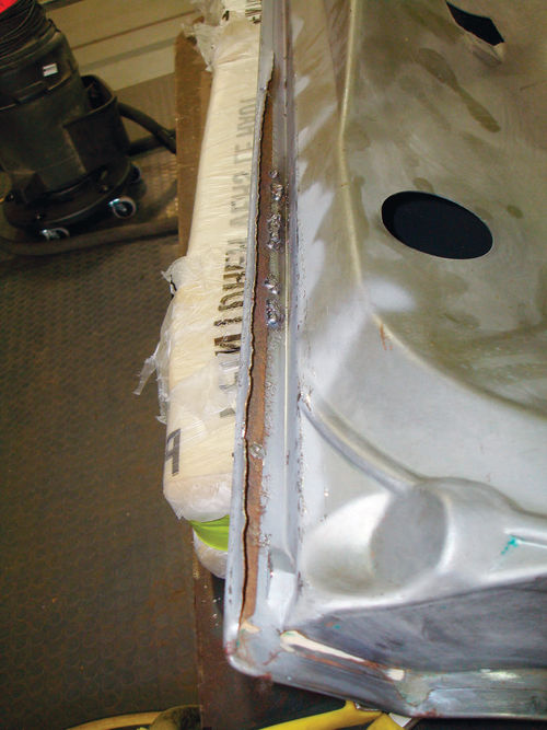
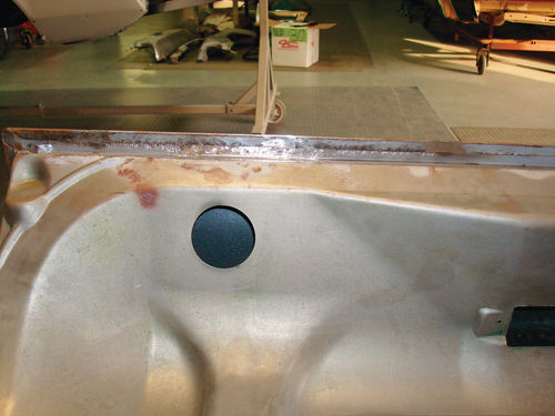
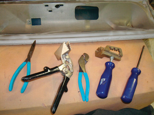

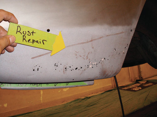
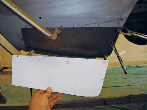
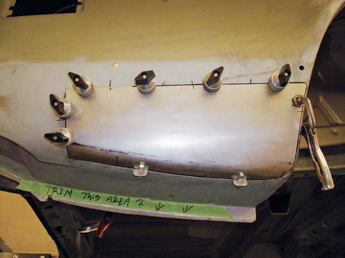
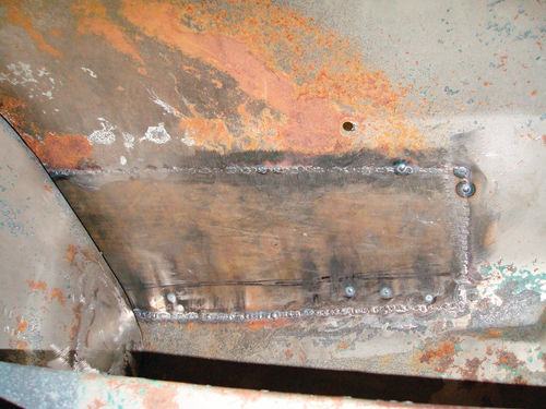
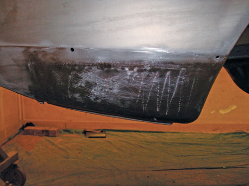
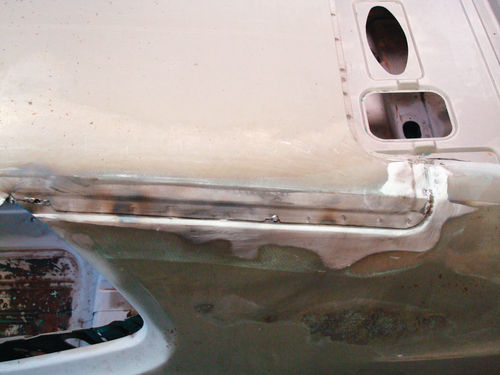
Photo 23. We then cut out new metal in the same gauge as that of the original metal. Then lay the patch on top and scribe a line on the outer edge of the new metal. Next, using a cutoff wheel you trim right on the line exactly. As seen we have panel clamps installed to hold it all in place. It is a common mistake to get the panel gap too wide or too tight. If it is too tight, 1 ⁄16th or less, then when the heating process of welding takes place it will push the two pieces together and swell, thereby pushing out the welded area or forcing it in, creating a dip. Too large a gap, around 1 ⁄8 th and larger, and the MIG wire will not fill the void requiring too much welding and raising the chance of warping the panel.
Photo 24. Once welded you want full penetration like this shows on the back side. Once we run a grinder over this just a bit and then media blast it we can prime it for no repair detection.
Photo 25. After full welding and then grinding it smooth it is ready for a skim coat of polyester fill to perfect the panel.
Photo 26. Another area often overlooked is the panel seams where factory lead was applied like on this quarter panel-to-roof seam. These usually have traces of rust in them once the lead has been heated and scraped away. Unless you have extreme knowledge of lead repairs and are able to lead without any traces of acid left over then the following method will work best. It will also stiffen up the panel and be a much faster repair at that.
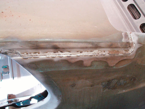
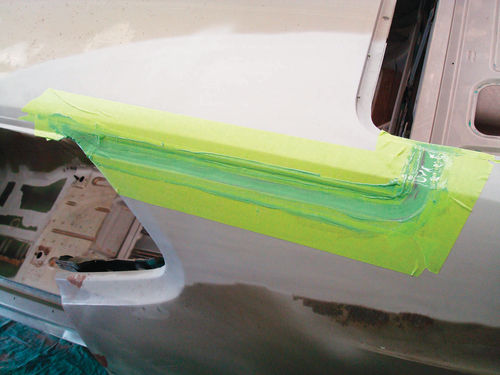
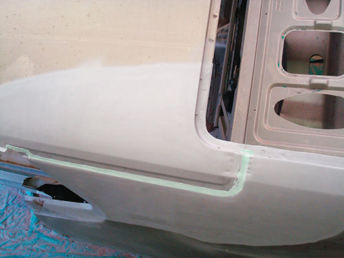
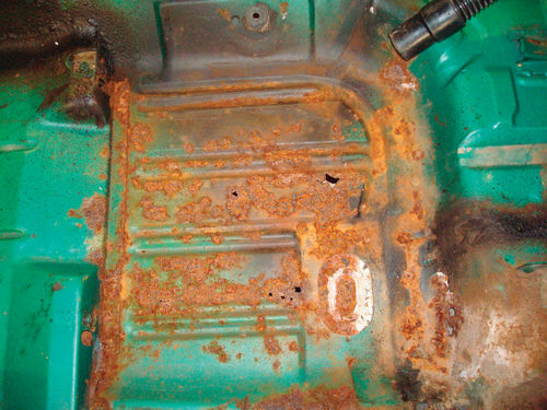
Photo 27. Next we fully weld the seam then grind the welds smooth.
Photo 28. After we media blasted we then apply a thin coating of 3M #1838 green 2-part epoxy for permanent sealing. Note the tape to confine the epoxy. Also note that 1 ⁄6 th thick is all that is needed.
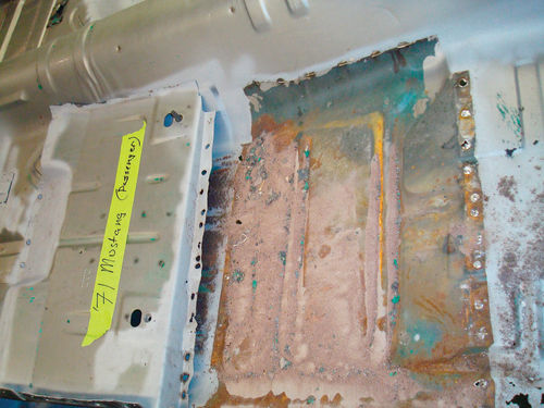
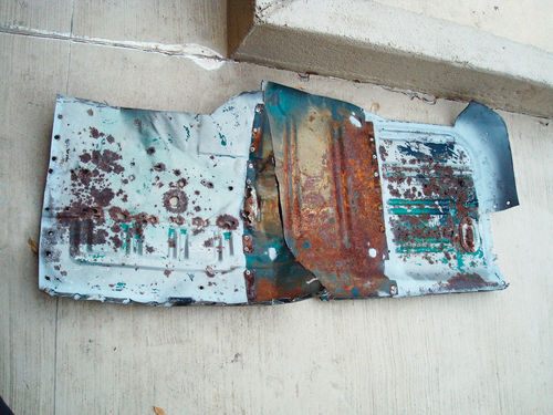
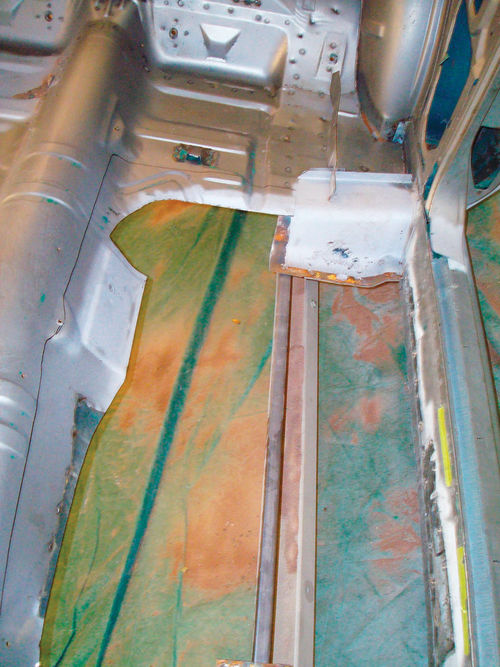

Photo 29. Let it dry overnight then sand it down and peck it with the media blaster and then apply a thin coat of Rage Extreme from Ever Coat. You now have a permanent repair that will never rust. EVER!
Photo 30. Floors are the next common problem. If you pull out the carpet more than likely you will see thin and rusted out holey sections.
Photo 31. On full-frame cars there are braces that run from side to side and most of the time there are no seat risers to deal with. On uni-body cars where the frame is welded in to the floor such as with our demonstration car you have to remove the riser. If at all possible we like to keep the original risers because repro units are often inaccurate in height and angle which will make the seats sit crooked. NOTE: Take height measurements from the edge of the rocker panel where the step plate was to the transmission hump and also front to back so you know the proper repositioning specs. If repros are your only alternative you may need to shim them to achieve these measurements.
Photo 32. The next order of things is to remove the rusted floor sections as close and tight as possible past the rusted sections leaving as much room as you can to trim and fit the new floor.
Photo 33. We placed the new repro floor on top of the original and the marker line shows plenty of material to work with. The shapes and grooves that the factory floor was stamped with are the main concern. We want to minimize going through them as much as possible because that would require more fitting and smoothing around them on the bottom side. The goal is as many flat areas as possible. This is important when you are trying to replace the floor with no repair detection and also to make the best time possible during the repairs. As seen we cut the old floor out to avoid as many stampings as possible.
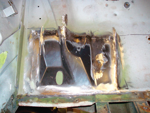
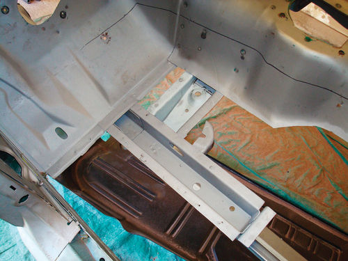

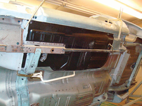
Photo 34. Our new floor would cover this entire toe board, however this was the only area rusted on the toe board. The original floor overlapped the toe board so we want to keep that original. The repro floor is only made in one section so choosing to install this small section is faster and smarter because then we will simply lay the main floor down on top of this seam as per the factory.
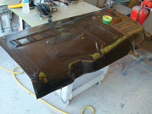
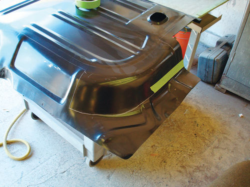
Photo 35. Once done we simply grind it flush and you have a nice repair.
Photo 36. Now that we have the smaller section repaired we media blast the outer perimeter including the frame rail to remove all traces of rust.
Photo 37. Next we Zinc Chromate prime the entire blasted metal area. This will eliminate any corrosion in the future.
Photo 38. We then clamp the panel in place for a tracing all around the unibody frame rails. We then carbide scribe around the perimeter of all the bracing; approximately 1 ⁄2-inch inside the scribe marks is where we will drill holes for welding. That will put the weld dead center on top of the frame rail and bracing. NOTE! As a safety measure we tack welded a piece of tubing to keep the frame rail from moving in and out or front to back during the procedure.
Photo 39. With the floor panel pulled back out you can see the trace marks where we will measure inside 1 ⁄2 inch to drill the holes for welding the panel onto the frame and braces.
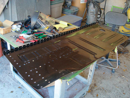

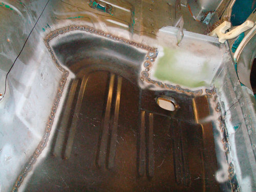
Photo 40. In addition we traced around the old floor where it meets up with the new one and we are tape marking where to cut. This will allow us a butt fit to weld the new floor in.
Photo 41. Holes were drilled every two inches.
Photo 42. We have panel clamps in place where the old and new panels meet. We also used self-tapping screws to press the new floor in tightly against the frame and braces before we started welding. This way when you look at the floor from the underside it will be super tight against the frame and bracing.
Photo 43. Once we had it all fitted, we welded it up solid. Only weld 1 ⁄4- inch long beads then move on to another section and back to another area, sort of like chain links, to allow cooling between rounds.
Photo 44. As mentioned earlier we removed the odd seat risers. There are reproones available but they can be inaccurate so choose wisely when replacement is needed. We like factory parts whenever feasible. These original seat risers require a repair section on the flange so we are ready to weld them in solid.
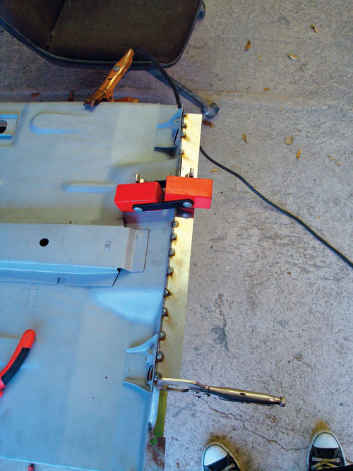
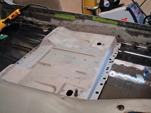

Photo 45. Installed we align to our measurements and mark the locations.
Photo 46. As seen on the ghost silhouette we spot blasted the old risers through the old welds we drilled out beforehand so we could get good welding penetration and mark its proper location at the same time.
Photo 47. Again we installed self-tapping screws to get it tight to the floor and then welded it in solid. Once it was welded we simply removed the screws which left a 1 ⁄8th hole and then welded them also.
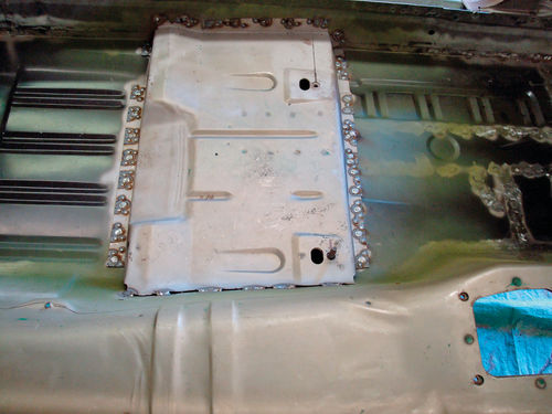
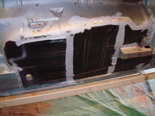
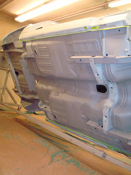
Photo 48. The floor is done and looks good. We usually hold a light on the opposite side and check for any pinholes where the light shines through and then touch them up, if there are any, to finalize the repairs.
Photo 49. Next we fully media blast and then epoxy prime the entire floor so we can go on to the next step of the build.
RESOURCE
Jeff Lilly Restorations
11125 f. m. 1560
San Antonio, TX 78023


