
Balance Tires With Retro Style, Pt. 2
First We’ll Use Our Hunter Tire-Spinner to Balance Drive Wheels. Then We’ll Work With a Strobe Light System.
EDITOR’S NOTE: LAST month we worked with a Hunter TuneIn tire-spinner on non-driven wheels. There were nine images with the previous installment, so we’ll start here with Photo 10.
Balancing the Drive Axle Wheels
Now it’s time to check the driven wheel(s) using the vehicle’s own power. Remember, if the vehicle has been sitting with its wheels on the ground for any length of time, take it for a short drive to round out any temporary flat spots before proceeding.
The following are Hunter’s suggested lifting procedures:
Rear-wheel drive with standard differential, “jack the car under the frame at the factory approved jacking point, ahead of the rear wheel to be balanced.” Chock the three remaining wheels.
Front-wheel drive, “jack under the frame, at the factory approved jacking point, behind the front wheel to be balanced.” Chock the three remaining wheels.
Rear-wheel drive with a limited-slip differential, “jack the car under the frame at the factory approved jacking point, ahead of the wheel to be balanced. Jack up the opposite rear wheel under the axle near the wheel and remove that wheel. (On vehicles with independently-sprung rear wheels, jack only at the factory approved jacking points.) Be sure to replace at least three lug nuts to keep rear drum from coming off. Make sure jacks are secure.” Chock the two front wheels.
In all cases, the wheel to be balanced should be raised about 2" off the ground.
As we discussed last month, verify that the tire/wheel runout is acceptable, and perform a pre-balance check. If a vibration is evident, mount the adapter and head to the wheel. Have an assistant start the engine, put it in gear and SLOWLY depress the accelerator. If the vehicle tries to move, you have just discovered that it has a limited-slip differential. In that event, reposition your jacks and follow Hunter’s lifting procedure.

With a limited-slip differential, don’t exceed 80 mph on the speedometer; or 40 mph with a conventional single-wheel drive. The balancing procedure is the same as was previously performed on the non-driven wheels. Once the wheel is “tuned-in,” place the vehicle in neutral and turn off the engine, letting the wheel coast to a stop. The head and adapter can now be removed and the weight applied.
If there’s a vibration that persists after balancing both tires on the drive axle, the problem is likely elsewhere, possibly a drive line vibration. Look for the following: worn-out/loose universal or constant velocity joints or even a badly worn transmission extension housing bushing could be the culprit. A bent driveshaft is also a possibility, and should be easy enough to spot by simply watching it rotate while you still have the vehicle raised. But before putting any part of your body under any vehicle, make certain it is properly supported on jack stands. Also the driveshaft itself could be out of balance. That can usually be corrected with the aid of most model strobe balancers as long as they have a detachable strobe light. I will get more into that later in this series.
Hunter no longer offers the Tune-In system, so you will have to settle for used equipment. Hunter does, however, still sell an 8 HP spinner and strobe light which can be seen on their web site (hunter.com). While they don’t disclose the price (you will need to contact one of their reps) I can assure you it’s many thousands of dollars. They are primarily marketing it for large trucks, but it can be used on most anything, and it’s powerful enough to even be used for spinning the drive wheels of a vehicle. Strobe balancing is, of course, different than what we have discussed to this point.
Strobe Light (Electronic) Balancing
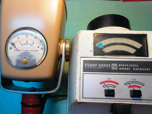
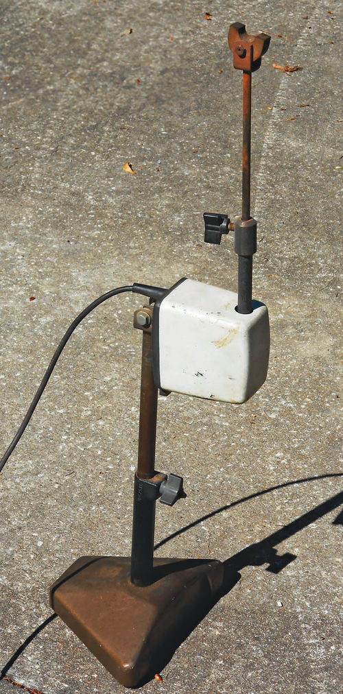
Although Stewart Warner offered both a strobe and a mechanical balancing system, their strobe light balancer is all that I have ever encountered, and it’s by no means common. Frequently their strobe equipment is referred to as the “Alemite Electronic Wheel Balancer.” Some of this equipment can date back to the 1940s, and while all strobe systems essentially function the same way, they can look very different. Photo 10 is a model 7054-1, and the paperwork that I received with it indicates it was made before 1952. This early ’50s machine has a small wheel spinning unit (lower right in Photo 10), with the strobe light and meter permanently mounted to a separate rolling base. I have another similar unit, model #7054, that is called “Stewart Warner Electronic Wheel Balancer.” Its serial number is considerably lower, so an educated guess would be that the “Alemite” name came into use around 1950-51, and was used for two or three decades, and then the Alemite name seems to have disappeared.
Regardless of the equipment used, the magnetic pickup is typically positioned close to the tire, under the lower control arm (or solid axle) when checking the kinetic balance (up and down vibrations); and then against the brake shoe backing plate for checking the dynamic balance (side-to-side vibrations). The strobe light will flash when the heavy spot passes the magnetic pickup. The meter will verify when the vibration is at its peak, and act as an indicator of how much weight is needed to correct it. (Obviously, that’s the abbreviated version of how this system operates.)
Let’s start again with the non-driven axle, which translates for most of us to doing the front wheels. Raise the vehicle in the same manner as was performed for the Hunter Tune-In system, and then inspect the tire to be balanced for excessive runout. Once verified, perform the pre-balance check. To this point the procedure is identical in every way
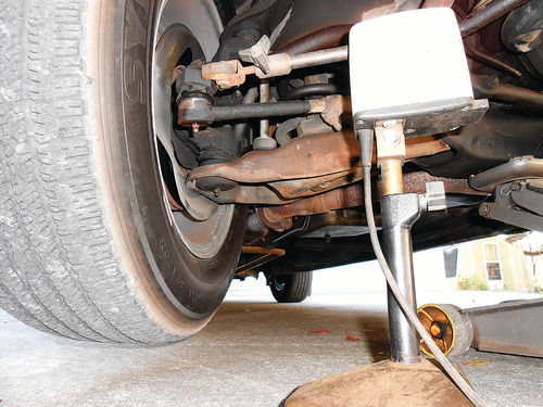
If it’s determined that the wheel requires balancing, the next step is to remove any existing wheel weights and wheel cover if needed. The magnetic pickup is then positioned where it will sense vibration. The pickup sends a signal to the strobe light and meter, so it must make good contact with a relatively clean metal surface. If there is an accumulation of oil and grease, clean the area before positioning the magnet. Loosen the thumb screw (or collet) to extend the pickup shaft to the height needed and then re-tighten it. Photo 11 shows it positioned under the lower control arm, close to the ball joint. Positioned like this, it is set up for kinetic (up-and-down movement) balancing. If your vehicle has a straight axle up front, place the pickup beneath it, close to the wheel. As you can see in the photo, with the spinner in position things get somewhat close, so it’s a good idea to position the spinner first, and then the pickup. Some pickup units can be positioned either laying down like the one shown in Photo 11, or the head can be tilted back, allowing it to be used in the upright position for vehicles with greater ground clearance, if needed. This one, however, does not tilt.
Do a test by bumping the top of the tire with your hand. That should make the meter move and the strobe should flash. This verifies that you have good contact with the pickup.
The meter on the strobe system has a high and low sensitivity scale. For most passenger vehicles, choose the high sensitivity; large and older trucks, however, might be better served with the low setting. The meter indicates the degree of vibration being felt and the graduations on the scale are used to approximate the ounces of weight needed. Photo 12 shows two typical meter scales; the strobe on the left is an older model #7058, while on the right is model #7066, one of the later designs, probably getting near the end. The sensitivity adjustment switch is located on the back end of the plastic strobe housing on the #7058 unit, directly in front of the handle. If you look closely you might notice a little bump in that location; that’s the sliding switch. The #7066, on the other hand, uses two buttons that are plainly visible on the top of the unit.
For passenger vehicles Stewart Warner suggests using 1 ⁄2 oz. of weight per meter graduation. This is only an approximation, as the required weight will vary with tire size, but it’s a starting point. After balancing the first tire on the vehicle you will better know the proper weight per meter graduation for the remaining wheels, assuming they are all the same size tires.
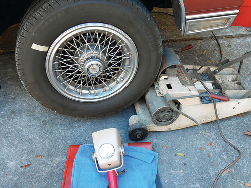
Initially a reference point is needed on the tire to see when the strobe flashes. The valve stem can be used, but marking the tire with chalk or a few inches of masking tape is much easier to see. This reference point can be made anywhere on the tire as you see in Photo 13. The strobe shown in the photo is an older Stewart Warner 110V unit, probably from the late ’50s or early 1960s. It’s designed primarily for passenger vehicles and the electronics for the strobe and pickup are contained within the spinner unit itself. Later models incorporated all the electronics into the strobe, which explains why the strobe shown to the right in Photo 12 is considerably larger. But I digress.
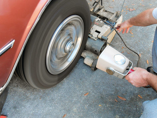
Have the strobe light pointing at the wheel, and then start the wheel spinning as is shown in Photo 14. You will notice the strobe light starting to flash, which will make the wheel appear to be standing still. When the wheel picks up speed, the needle on the meter will start to rise if there is an out-of-balance condition. As the speed continues to increase, the meter will reach a point where it peaks, and then starts to decline. Continue spinning the wheel slightly beyond this peak, until you have noticed this drop-off. At this point pull the spinner away from the wheel and watch the meter closely. As the wheel slows the meter will once again start to peak. At this moment note both the meter reading and the location of the reference mark on the tire. The best approach is to visualize the tire as though it were a large wall clock. If the reference mark is viewed down at the bottom of the tire, that’s 6 o’clock; while straight up at the top would be 12 o’clock, and so on. Using this frame of reference will make it easy to remember the mark’s location. Now allow the wheel to come to a stop, or use the means provided by the spinner to gradually slow it. Position the wheel so that the reference mark is located where it was when the meter was at its peak.
Weight Placement
Using the reading on the meter, estimate ½ oz. of weight per graduation, and apply the weight at 12 o’clock on the outside of the rim. Should the weight be greater than 3 oz., split the amount and apply half on both the inside and outside of the rim at the 12 o’clock location. Spin the wheel as before and note the meter reading. If it remains in the green zone, the kinetic balance is now completed, but if it rises above it, again note the location of the reference mark at the peak meter reading.
Once the wheel has come to rest, position the reference mark where it was at the peak meter reading. Now note the location of the wheel weight. If it’s located at 12 o’clock, the weight is too light, and will need to be increased, while 6 o’clock is just the opposite, the weight is too heavy. Increase or decrease the weight and keep it in the same location. How much is necessary will be determined by trial and error. With practice, your ability to estimate weight will improve.
If the weight is located on either side at 7-11 o’clock or 1-5 o’clock area, shift the weight 2" toward the top of the wheel. Remember, if the initial weight was split on both sides of the rim, move them both the same amount so that they remain lined up.
Repeat the balancing process, rechecking after each adjustment until the meter remains in the green zone. Once completed, it’s time to check the dynamic (side-to-side) balance.
Dynamic Balance Check
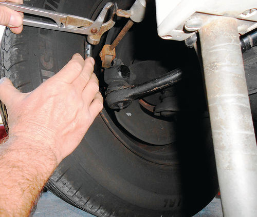
Rotate the steering wheel so that the front of the tire to be balanced is positioned all the way out at a “full turn,” and then back up ¼ turn of the steering wheel. It will remain in this position throughout the balancing procedure. This will give you easier access for both positioning the magnetic pickup, and placing the weights on the rim. If the vehicle’s steering wheel doesn’t lock in position with the key off, it’s highly advisable to use a steering wheel lock to keep the tire from wandering. Remove the magnetic pickup from under the control arm (or solid axle) and reposition it against the brake shoe backing plate. If there is a heavy build-up of dirt and grease, clean the area and establish a good contact. If the tie rod connection to the steering knuckle is located in front of the control arm, it may block access to the backing plate. In that event, the magnet can be placed against the steering knuckle where the tie rod connects, as seen in Photo 15. (This is the pickup that came with the SW #7066 strobe. Should there be a special need, the head of this pickup can be pivoted back, and it will extend 30" high as you can see in Photo 16).
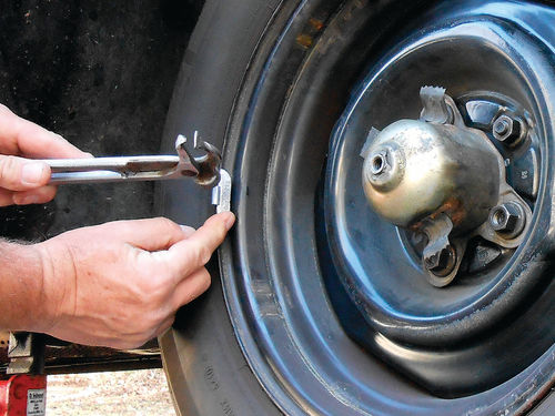
Start the wheel spinning using the tire spinner, but it’s not necessary to go as fast this time. You only need about half the wheel speed used during the kinetic balancing, then disengage the spinner and let the wheel coast. If the meter remains in the green, there is negligible dynamic unbalance, and this wheel is good. If it goes beyond the green, wait until the peak reading is reached, and note the reference mark location on the wheel. If needed, repeat the tire spinning procedure again to verify the peak meter reading, and the reference mark location. As we did before, slowly stop the wheel, and then position the reference mark where it was viewed at the peak meter reading. Apply 1 ⁄2 oz. of weight per meter graduation (or whatever you have determined is best for the wheels you’re working on), but this time the weight will be split and placed in two locations opposite each other. Apply half the weight to the inside front of the rim next to the pickup magnet as is being done in Photo 17, and then place the other half to the outside of the rim, 180° around the tire as seen in Photo 18.
Next, we’ll continue our discussion of dynamic balancing, look at drive shaft balancing and then offer some tips for locating and buying a tire-spinning balancer.


