
Balance Tires With Retro Style, Pt. 1
Tire-Spinners Were a Popular Tool Four to Six Decades Ago. It Takes Time to Master Them, But It’s Well-Spent.
When buying new tires most people have them computer balanced at the time of purchase. That makes sense, and works fine most of the time. As for myself, I prefer to carry my old tires and wheels into the tire store, leaving the vehicle at home, safe and secure on jack stands. This certainly isn’t because they are rare or highly sought-after vehicles; I’m just funny about other people driving…or doing anything to them. And when it comes to balancing, the tires return to my garage for that task. This all started many years ago after a new-tire purchase led to a vibration in my ’86 Chevy Caprice.
Long story made short, after a couple of unsuccessful visits back to the tire retailer, I finally returned home and used my old bubble balancer. It outperformed the tire store’s computer balancer, alleviating the vibration problem. OK, maybe that’s not a fair statement. The difference may be due to a lack of equipment maintenance and proper calibration on the store’s part. Or possibly it has to do with motivation. The operator may have had more important things on his or her mind…like plans for the evening.
On the other hand, I take my bubble balancing seriously, and vibrations are unacceptable.
Reaching Back for Another Approach
There is almost a ritual when it comes to using the bubble balancer in my garage. There is a specific location marked off where I prefer to use it; it’s then leveled, and once it is, the head is unlocked to float freely and adjusted again if need be to center the bubble. The centering cone and platform the rim rests on is each marked with a Sharpie; this is used as an index point. These are always lined up with the head release lever, and when the wheel is placed on, the valve stem is also lined up with this same mark.
While all of this “lining up” isn’t required, it only takes a moment, and if nothing else, it makes the balancing procedure exactly repeatable should there be a problem.
There is never a fan blowing or a breeze that could disturb the balancer; and in the summer in Florida, that’s dedication. A good deal of time is taken to set up, and actually balance each tire. My thoughts are focused entirely on the task at hand. So if I can obtain more effective results out of a simple bubble balancer that is limited to static balancing, imagine what a properly calibrated computer balancer might yield me. Unfortunately, they are a bit out of my price range. There is, however, some older tire balancing equipment out there that does great things! I’m talking about equipment that spins the tire and balances it while it’s on the vehicle. Most readers are probably familiar with this type of tire balancing, but there may be a few that aren’t. Some such equipment made by Stewart Warner dates back to the late 1940s, and probably there is some predating that. It was popular into the 1980s, and then seemed to fade away. I can recall a billboard off I-75 in north-central Florida back in the 1970s and ’80s that advertised “High Speed Tire Balancing This Exit.” It even pictured an outline of the tire spinner machine.
There are several manufacturers, and the means of balancing varies, but the one thing that they all have in common is they will balance the entire assembly, not just the tire and rim. In other words, if a brake drum, rotor or wheel hub is out of balance, it will be corrected in the balancing process. The modern computerized tire balancer can only balance the tire and wheel once they’re removed from the vehicle.
Learning Takes Some Time
Not having to remove the tire from the vehicle may sound as though it’s a big time-saver, but usually that’s not the case, the exception being with large vehicles, where tire removal is considerably more time-consuming than on a passenger vehicle.
While a person can learn to operate a computer tire balancer in probably five minutes, it takes considerably longer to master using any of the on-vehicle type balancers. With practice the operator becomes more and more proficient; however it can still be a time-consuming process. This and the fact that some newer vehicles don’t lend themselves well to “on-vehicle balancing” probably led to its decline. A good example is my friend’s 2005 Honda Odyssey. Of course this is a front-wheel drive vehicle, and while spinning and checking the rear wheels was no problem, the front was another story. Almost all “on vehicle” balancing equipment uses a wheel spinner to rotate the non-driven wheels, and when balancing the driven wheels, the vehicle uses its own power to do so. With the Odyssey’s front wheels elevated off the ground, the engine was started and the vehicle was placed in drive. I then instructed my friend to start accelerating, but nothing happened. The wheels continued to rotate slowly and the engine remained at idle. My friend (while laughing) advised me that he had the accelerator pedal pressed to the floor, while the engine was still idling nicely. Certainly this must have something to do with traction control, or something well beyond my knowledge. Since it’s obviously controlled by a computer, possibly there is a means to temporarily disable this feature. If it were my vehicle, I would have found the answer to that question, but my vehicles are no newer than the late ’80s, and for that matter all are rear-wheel drive. My point here is that this new generation of vehicles may often have issues that will fight you. Even if this feature in the Honda Odyssey could be temporarily disconnected, it would likely be considered entirely too time-consuming in the average shop environment for routine tire balancing. On the other hand, for individuals working on their own vehicles, the clock shouldn’t be an issue.
So, How Do They Work?
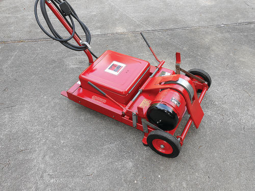
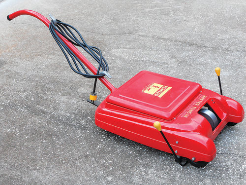
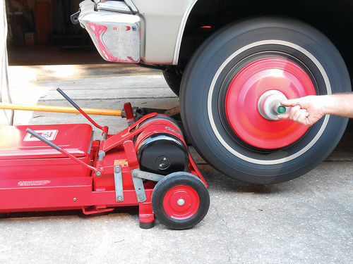
All manufacturers use an electric motor mounted in a rolling frame to spin the “non-driven” wheels of the vehicle. Shown in Photo 1 is a unit manufactured by Hunter Engineering Co. It has a 4HP, 230V, 20A motor, and should be capable of spinning most anything you encounter. They also manufactured a smaller unit that uses a standard 110V household outlet as seen in Photo 2. Its motor is labeled 1.25HP, 14.5A. If you need the convenience of 110V and desire a smaller and lighter-weight machine, this is it. While certainly not as zippy as the 4HP, it will still do the job, even on light trucks. The body is made of cast aluminum and can be more easily damaged, so make sure to inspect for cracks before you buy. There are other manufacturers out there, Stewart Warner for one. However, the machines made by Hunter seem to show up the most frequently.
The actual tire balancing is accomplished either by mechanical means, or by using a magnetic pickup and strobe light. Both systems have their strengths and weaknesses—Hunter Engineering and SW offered both.
Note: should there be brake service needed that will require replacing or turning drums or rotors, do that first. Remember that this system will be balancing all of the rotating mass. Also remember that if a wheel needs to be removed from the vehicle after balancing has been completed, its location should be indexed so that it can be replaced exactly where it was otherwise it will require rebalancing. A good method is to put a dot of paint on the end of the wheel stud that lines up with the tire’s valve stem. In instances where there are brake drums (or rotors) that “slip on,” use a paint marker to mark the drum/rotor with a circle around that same stud’s hole. Now the wheel can be replaced in its original orientation.
The Hunter Tune-in System & Some Cautions
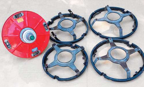
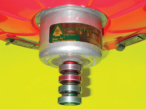
Hunter popularized a system called “Hunter Tune-In.” This was a mechanical method that utilized wheel adapters and a calibrated head that mounts to the adapter. Photo 3 shows the calibrated head to the left, and the universal 13" through 16" wheel adapters to fit conventional steel wheels.


There are always safety issues to be aware of before getting started, so here are a few: Some vehicles connected their speedometer cable to one of the front wheels, usually the driver’s side. Both early VW and Olds Toronado come to mind. These electric wheel spinners can easily exceed the range of the speedometer and cause damage. Check the vehicle you are working on to be sure the speedometer isn’t wheel driven. If it is, either disconnect it or have a helper monitor the speedometer to avoid accidentally pegging the needle.
In addition, make certain the tires rotate freely before attempting to use the electric tire spinner on them; inspect and make sure the tire being spun is free of small pebbles and debris; the vehicle is properly and securely raised on a jack, or better yet placed on jack stands; don’t allow anyone to stand in line with the spinning tire; always make certain the wheel adapter and calibrated head are secured to the wheel and won’t end up taking flight. With both front wheels elevated off the ground they will sometimes tend to move or steer. For this reason it’s a good idea to secure the steering wheel using a steering wheel lock or you can improvise.

I haven’t talked about it, but obviously your front end must be in sound condition. It’s pointless to be worried about wheel balancing if your suspension or steering linkage is worn out. As well, the wheel bearings can’t exhibit any looseness. If needed, snug them for the balancing procedure, and then readjust them to the proper adjustment once the balancing is completed. Most vehicles require some minimal free play in the bearings to allow for expansion once they warm up. Check the service manual for your vehicle’s proper adjustment.
Pre-Balance Check
Before attaching anything to the wheel, do a pre-balance check. The vehicle first must be driven for a few miles to warm up and round out the tires. Next raise both of the vehicle’s non-driven wheels 2" off the ground.
Make sure the tire will rotate freely by hand. If not, the brake shoe adjustment may need to be backed off, or on disc brakes, the pads pushed back slightly, away from the rotor.
Note: Once the balancing of the non drive axle wheels has been completed, remember to pump up the brake pedal several times on vehicles equipped with disc brakes and/or readjust any brake shoes.
At the same time check for any excessive runout, both radial and lateral. Any stationary object (for example, a cinderblock) can be positioned close to the tire and used as a reference. Usually .060" (or 1 ⁄16") is considered the maximum allowable radial and lateral runout for today’s tires. However, some 1950s Hunter literature indicated up to .125" (1 ⁄8"), and SW indicated up to ¼" for large truck tires. Even if a tire is perfectly balanced, excessive tire and/or wheel runout will transfer that bouncing motion through the chassis and the driver will feel a vibration. Having the tire(s) trued so that they run concentric with the rim, or replacing the bad tire or rim are the options here.
At this point, the electric spinner unit is used to briefly spin the tire. If there isn’t any vibration felt or abnormalities noticed when spinning the wheel, that wheel is OK. This is a simple test that can quickly isolate vibration issues to a specific wheel. If vibration is detected, balancing is required.
Balancing Procedure
Normally you would remove any existing wheel weights, but for this demonstration I did not.
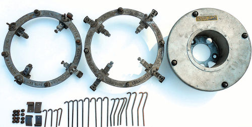
Remove the wheel cover, select the proper adapter and position it in the rim. In addition to the universal adapters seen in Photo 3, there also were special adapters to fit wire wheels; Cadillac El Dorado front-wheel drive; early Monte Carlo wheels; early VW, and so on. Photo 4 shows several of these special adapters. To the left is #100-A, and in the center is #00-A. These adapters are for front-wheel drive and wire wheels. They are adjustable to fit different diameters, #00-A has longer adjustable legs, fitting wheels up to 17". While at first glance they otherwise look the same, the difference is the point where they contact the rim. The #00-A is pictured in literature fitting Jaguar “knockoff” wire wheels, and it would appear #100-A fits Olds Toronado and Cadillac El Dorado front-wheel drive vehicles. The hooks and clips seen at the bottom of Photo 4 are used in all applications to secure these adapters to the wheel. In most cases they are positioned directly opposite each other and the hook is inserted so that it secures through one of the holes in the rim, and then inserted through the flat clip which is positioned over the adapter ring. A knurled “finger nut” is threaded on and snugged. To the far right is the adapter for early Monte Carlo rims. It’s secured with the wheels’ lug nuts.
Fitting the Adapter and Calibration Head
The universal adapters, however, fit most of the steel wheels of that time. They have a slight cutout to line up with the valve stem so it will completely seat. Notice in Photo 5 each universal adapter has two wheels that resemble a star wheel for adjusting brake shoes. The two small red arrows point to one of them. Just as with the star adjuster for brake shoes, these will either expand or contract the diameter of the adapter. Also notice in the left of the photo is one of the two locking levers that expands and secures the adapter to the wheel. The red flag is to remind you that the lever is in the unlocked position, and is unsafe to spin.
With the red “flag” facing outward on each locking lever, both adjuster wheels should be rotated equal amounts until the adapter fits snug within the rim. Now rotate both locking levers inward until they stop, securing the adapter to the rim as seen in Photo 6. The red flags should no longer be visible. Should the levers not fold down completely, back off each adjuster wheel equal amounts until they do. Give the adapter a good tug to make certain it fits securely.
Once the adapter is tight and secure, the calibration head (referred to as the “Balancing Instrument Disc” in the instructions) is positioned over the four studs of the wheel adapter, and secured by folding down the four locking levers as shown in Photo 7. Again tug on the head to make certain it is properly fastened to the adapter. Photo 8 gives a close view of the calibration head and knob tower. The numbers you see indicate the ounces of weight to be applied. The increments in between each number equal ¼ ounce. The arrow to the left indicates where the weight needs to be applied. When the wheel is spun, knobs on the calibrated head are manipulated until the vibration is eliminated. The two inner Red knobs increase and decrease the amount of weight, while the two outer Green knobs control the weight’s location, moving the weight either clockwise or counterclockwise around the wheel.
Prior to spinning the wheel, Hunter suggests adjusting the red knobs until the indicator points to 1½ ounces, and use this as an initial means of balancing. The wheel spinner is centered up with the tire, and the motor engaged. They suggest spinning the wheel only “slightly above the point of maximum vibration, but no faster.” Use the bumper or other part of the car to judge vibration. Some operators like to place their hand on the fender with one finger raised to judge the vibration; an open car door can be a good indicator, and even a small glass of water on the fender has been used.
In Photo 9, I am momentarily pinching one of the green knobs. This is probably better described as a short, quick, squeeze of the knob between the index finger and thumb. This will move the weights around inside the head until the light spot is found and vibration is reduced. To fine-tune the location they suggest going slightly beyond the point of least vibration, then using the other green knob to back up to the “ideal spot.”
Once the location is determined, pinch one of the red knobs to change the amount of weight. If the vibration worsens, pinch the other red knob. As before, fine-tune the adjustment by going back and forth between the two red knobs. If some vibration still remains, increase the wheel speed slightly, and use both sets of knobs to touch up, and obtain the best balance. Now it’s time to apply the weight.
On this Hunter wheel spinner, the levers with the red grips mounted on the side frames are used to slow the wheel. Pulling either one toward the rotating tire will bring the heavy metal “brake plate” in contact with the wheel.
Slow the wheel gradually, not abruptly, and never use the vehicle’s brakes. You don’t want your neighbor to see the calibration head go flying and report a UFO sighting. Personally, I let it come to rest on its own without using the brake at all, it only takes a minute. Locate the “add weight here” arrow and make a mark on the tire using chalk to correspond with it. Then remove the calibration head and possibly the adapter to obtain adequate clearance to hammer on the weight.
If All the Vibration was Eliminated During Spinning…
Apply the amount of weight indicated to the outside of the rim at your chalk mark. This wheel should now be finished.
If The Vibration was Not Completely Eliminated…
Mark the tire as described before at the “add weight here” arrow, but this time on the inside of the tire. It’s usually easiest to make the initial mark on the outside, then use a small square to line up and extend the line over the tire’s tread, and then down the inside sidewall. Rotate the tire and position the steering wheel to where it gives you the easiest access to make the chalk mark.
If all the vibration couldn’t be eliminated, or if the calibration head indicates more than 4 ounces is needed, try applying about half the amount of weight indicated to the inside of the rim (at the chalk mark), and repeat the tune-in procedure. To avoid any confusion, remove the previously made chalk mark from the outside of the tire. Finally, add the indicated weight to the new “add weight here” location pointed to on the outside of the rim.
If Some Vibration Still Remains…
Hunter calls this an “Extreme Dynamic Condition” and states “shift some of the applied weight to the other side of the wheel, directly across the wheel, and tune-in again.”
As a final test, each wheel should be spun again as we did in the pre-balance check, with the adapter and head removed. If a vibration is discovered, repeat the balancing procedure again, making sure the adapter’s star wheels are rotated so that the adapter is expanded out equally, and note that both the adapter and head are running concentric with the wheel.
Next, we’ll look at balancing the drive axle wheels along with strobe light balancing and weight placement.


