
A Front Disc Brake Conversion, Pt. 2
We’ve Shown You What’s Needed to Improve Stopping Power. Now We’ll Show You How to Assemble Those Parts.
LAST MONTH I laid out and went over the components needed to convert a front drum brake vehicle to front disc brakes. This month I’ll work on installing the disc brake conversion kit.
The conversion starts by removing the old drum brake assemblies from the car. Once you remove the drums, this is what you will find: brake shoes, springs and a backing plate (Photo 1).
You say you’re having problems getting the drums off?
On the backside of the backing plate, near the bottom, you will find a slotted hole. Hopefully this hole is capped with a black rubber insert to help keep dirt away from the brake shoes. Remove the insert, and with a shop light look into the opening. You will see the geared brake adjustment wheel. Use a flat-bladed screwdriver to reach through the opening and turn the gear counterclockwise. That will loosen the tension on the brake shoes and allow the drum to come off.
Note: On some vehicles you also will need to remove the spindle nut to pull the drum.
By the way, wear a dust mask as you work. In the old days, brake shoes were made of asbestos. Yeah, the dangerous stuff. Today, brake shoes are made of alternative compounds, but just the same, they create dust and it’s a good idea to not breathe it.
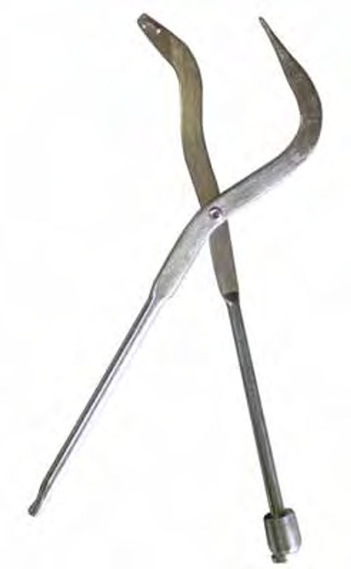

With the drums off, you can remove the brake shoes. All brake shoes are attached to the backing plates with springs. Remove all of the springs and the shoes will come off. Yes, they make a tool specifically designed for removing brake springs (Photo 2).
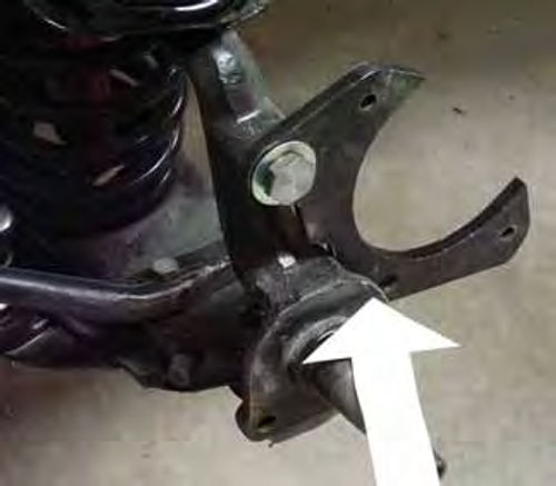
With the brake shoes removed, the backing plates go next. These plates will have two to four bolts, depending upon the vehicle, attaching them to the spindles. You will also need to remove the flexible brake lines from the connections on the frame rail tabs. The result of all this removal should leave you with a reasonable facsimile of Photo 3.
What you see in the photo is the spindle. It is attached to the upper and lower control arms at the ball joints and this might be a good time to grease those ball joints. But whatever you do, don’t remove the retainer nuts holding the ball joints to the spindle. Doing so can release the coil spring and result in crushed fingers, gouged eyes, broken bones, and the need for a long explanation at the hospital while they patch you up.
Starting the Installation Process
At this point I’m ready to mount the disc brake conversion brackets to the spindles. In case you forgot what the mounting brackets look like, here they are in Photo 4. I’ll use the left side as my working example and start with the larger “C” bracket and attach it to the top of the spindle using the large bolt provided in the kit (Photo 5). This bolt is started, but not tightened.
Next I attach the smaller bracket behind the spindle using the three bolts and the two spacers provided in the kit. On this car, two of the mounting bolts go through the two holes at the bottom of the spindle that were originally used to mount the brake backing plate and the tie rod extension. Those bolts then screw into the threaded holes in the small bracket.
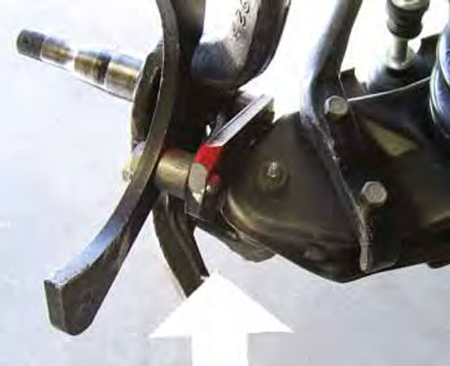
How do you know when the small bracket is mounted correctly? The flat, straight surface faces up. That allows the bracket to fit flush to the rearmost bolt hole in the tie rod extension and the curved surface to gently arch over the lower ball joint (Photo 6).
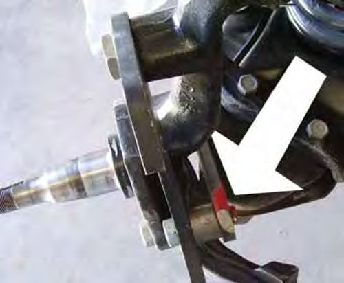
Where do the spacers go? The thin spacer goes between the small bracket and the forward bolt hole on the tie rod extension (Photo 7). The rearmost bolt hole does not use a spacer. The thick spacer goes between the small bracket and the “C” bracket (Photo 8). This is also where the third bolt attaches.
So here’s the layout of assembly. First is the spindle, behind the spindle is the tie rod extension, and behind that is the small bracket. Bolted to the top of the spindle and to the small bracket is the “C” bracket.
As I mentioned, the holes in the small bracket are threaded to receive the bolts provided in the kit. However, the bolts in the kit I purchased were too long and if they were left that long they would have interfered with the spindle turning radius. To stop this interference I installed all three of these bolts, snug tightened each one, measured the excess length extending beyond the small bracket, removed the bolts one at a time, cut them to length, added a little Lock-Tite to the threads, and reinstalled them (Photo 9). I also added Lock-Tite to, then tightened, the large bolt at the top of the spindle.


What does the completed bracket installation look like? Check out Photo 10. This should be the end result, the “C” bracket prominently visible and the small bracket completely hidden.
Rotors and Calipers
As I mentioned in the first installment, the rotors and calipers are stock items for the 1972 Chevrolet Chevelle. How do I know that? I asked. Mounting the rotors is a simple matter of installing the new bearings and rear seal into the rotors then bolting the rotors to the spindles.
You say you’ve never packed a wheel bearing? Here’s the trick. Scoop out a tablespoon-sized lump of axle grease into the palm of your hand. Hold the bearing upright with the opposite hand and force the bearing into the grease, taking care that the grease is pushed between each of the bearing rollers. The entire lump of grease should disappear into the bearing as you work. The bearing is now properly greased.
Install the rotor with the new bearings, snug tighten the castle nut, add the castle nut lock cap, insert a new cotter pin, then cover the castle nut with a new dust cap.
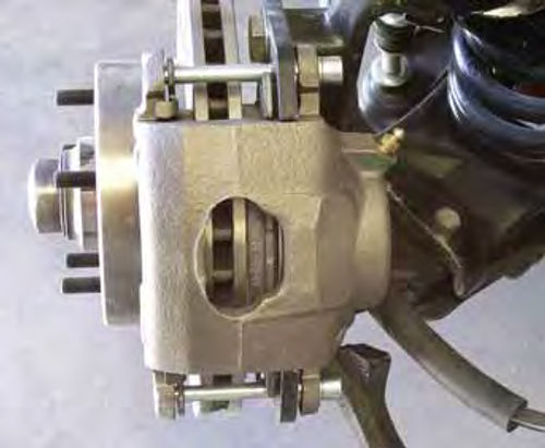
The calipers that come in the kit will be “loaded.” That means the calipers come with the brake pads already installed. That makes it a simple task of removing the two caliper attachment bolts from the calipers, sliding the calipers into place over the rotors, and reattaching the bolts (Photo 11).
There are a few other things to notice in Photo 11 as well. First, note the inner brake pad is just visible through the opening in the caliper. Second, note the two bolts attaching the caliper to the “C” bracket. Lastly, and this isn’t so obvious, notice that the caliper bolts are not only used to attach the caliper to the “C” bracket, they are also used to secure and hold the brake pads in place.
By the way, lubricate these bolts with a product like CRC Disc Brake Quiet (crcindustries.com). This prevents brake “growl,” a common occurrence caused by the brake pads chafing against the caliper bolts when the brakes are applied.
Brake Lines
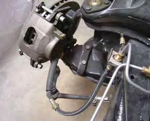
The first lines to be attached are the flex lines going from the frame out to the calipers (Photo 12). These lines take the place of the old flex lines with one end attached to the brake line tab on the frame and the other attached to the caliper. To attach these lines to the calipers, use the “banjo” bolts and brass washers supplied in the kit. Didn’t get the “banjo” bolts? Take one of the flex lines to your local parts store to be sure you get the correct-size bolts. Yes, these bolts vary in size, but your parts store will carry an assortment.

You also must make certain the new flex lines are long enough. With the lines bolted to the calipers and attached to the brake line tabs, turn the steering wheel fully right then left. The flex lines must be long enough that they are not stretched at any point during the turns.

They’re not long enough? Don’t panic, this is actually a common problem. Remove one of the flex lines and head back to the parts store. Your quest is for a longer flex line. If you are using GM calipers (most kits do) try an ’80s Camaro. This car uses longer flex lines. Did you remember to bring the “banjo” bolt? Yes? Good. Recall that I said there is a variety of “banjo” bolt sizes? Be sure yours fits the new brake line before heading back to the shop.
Master Cylinder Installation
Installation of the new unit is pretty cut and dried. Just remove the old master cylinder and replace it with the new master cylinder and power brake booster.
OK…there is a little more to the procedure than that.
Before removing the old master cylinder, remove the pin securing the master cylinder piston rod to the brake pedal. Why? Sometimes these rods are secured to the master cylinder with plastic retainers and they can be difficult to remove, even with the master cylinder on the bench. Releasing this pin at the pedal makes removal of the unit from the car much easier.
How do you get one of these pins out of the master cylinder? Vise-Grip pliers and some leverage should pop the pin out.
You say your new master cylinder and power brake booster unit came with a new rod already attached? Great. Is it the right length? The only way to know that is to measure both the old and the new rods.
Before mounting the new master cylinder and power brake unit, look for the bleeding instructions that come with the master cylinder. Most manufacturers recommend bench bleeding. I’ll talk about that in a moment. Once the master cylinder has been bled and you are ready for installation, don’t forget to hook up the brake pedal before moving on to the brake lines.

The Steel Brake Lines
Take a look at Photo 13—these fittings will not come in your kit. Don’t worry; your local parts store will have an assortment of brake line fittings. Just be sure the fittings you purchase are for brake line use and not for attaching the ice maker on the back of your refrigerator. They are not the same and will not work.
These are all 3/16 brake line fittings. From left to right, there’s one “T” coupling, one 90-degree coupling, and one of two union couplings.
The “T” coupling is used to join the right and left front brakes together as well as join both of those to the master cylinder. The union couplings and the 90- degree coupling will help you insert the proportioning valve into the rear brake line as well as help with the change of routing of the rear brake line.
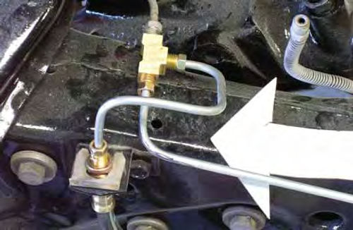
Now look at Photo 14. This is a close-up shot of how I routed the new front brake lines. Notice that both the line from the left brake and the line from the right brake go into the “T” fitting. Where does the third line go? Up to the master cylinder. Did you happen to notice that all of these lines are new? The line going over to the right brake is relatively short and easy to replace while the original line from the left side wasn’t going to work anyway. Besides, I like working with new stuff.
While I have you here, notice the open line near the top right of the photo. This is the original rear brake line. I’ll use the 90-degree coupling to help route this line back to the proportioning valve I mounted on the frame rail last month.
This will give me a rear brake line that doubles back onto itself, goes through the proportioning valve, then travels up to the master cylinder. That’s a lot of careful tubing bending, but it beats the heck out of replacing the entire rear brake line, a line that due to its length would have had to be custom-made.
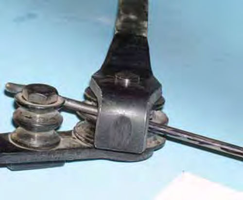
Which brings me to the need for bending the tubing. To bend the new brake lines you must use a tubing bender to prevent any kinking. Units similar to the one shown in Photo 15 can be purchased at your local parts store, on line, or from Eastwood (#49045). My advice is to purchase an extra length of brake line tubing and practice making bends. The best hint I can offer can be seen by looking closely at the photograph. Notice the black stripe I drew on the length of tubing? The black stripe indicates the outside of the bend. You’ll never make a wrong bend if you use this identifying technique.
“S” Stands for “Safety”
Recall that last month I showed you the coiled lines going up to the master cylinder. You don’t have to make these coils, but you do need to bend the lines going to the master cylinder into either “S” shapes or coils. How come? This is a safety issue that stems directly from crash testing done by the automotive manufacturers.
In a hard crash, things tend to move around. Having those coils or “S” shapes between the brake lines secured to the frame rails and the master cylinder secured to the body provides slack for that movement and prevents the brake lines from coming under stress and fracturing.
Note: Some conversion kits will come with the new brake lines already coiled.
“Might As Well Do This” Issues
While you are this deep into improving the braking system, why not go ahead and replace the rear wheel brake cylinders? They may be old; they may be leaking.
While you’re at it, you might as well have the rear brake drums turned and replace the old brake shoes.
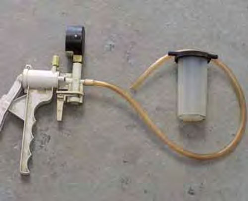
After that, you might as well go ahead and flush out the rear brake lines. I like to use clean brake fluid to flush out the lines. How do you go about doing that? You will need a brake bleeding vacuum pump similar to the one in Photo 16 (Eastwood #49040). Attach a rubber line (vacuum line) to the end of the brake line nearest the master cylinder, drop the end of the rubber line into a clean container filled with clean brake fluid, plug the line at the right rear brake, attach the vacuum pump to the line at the left rear brake and start pumping. When the fluid runs clean, the line is clean. Repeat for the right side, replace the wheel cylinders and secure all the line fittings.
Where’s the old, nasty brake fluid going? Into the reservoir on the vacuum pump, where it can be collected and recycled, just like you do with your old engine oil.
Bleeding the System
That starts with the master cylinder. The instructions that come with the new master cylinder will outline the procedure for bleeding the unit on the bench using two curved lines that attach to the master cylinder outlet connections and turn up and into the cylinder’s bowls.
With the unit clamped firmly in a vise, fill the bowls with clean fluid then depress the piston several times until no air bubbles can be seen coming from the submerged tubes. Remove the curved tubes, cap the bowl inlets and install the unit on the car. Where do you get the curved lines? You may need to purchase a couple of short lengths of brake line from your local parts store and bend them to specs. Just be sure the end fittings will screw into the master cylinder. Yes, adapter couplings are available to make the connection if need be.
With the master cylinder mounted on the vehicle and all lines secured, start the bleeding process at the left front wheel. Attach the brake vacuum bleeding pump to the bleeder connection located on the back of the caliper and operate the pump until the fluid runs clear; no air bubbles. Repeat at each wheel then test the brakes. The pedal should be firm and should not have to be pumped to achieve good brakes. If you have to pump the pedal, try bleeding the brakes one more time. Don’t forget to check the fluid level periodically as you bleed the system.
Adjusting the Proportioning Valve
Front to rear brake balance should be set so that the front brakes lock up just before the rear brakes do. This is a two person job, one to drive, one to watch the rear wheels. Make all adjustments at the proportioning valve at low speeds, a half turn at a time. When you are certain the setting is just right—the front brakes lock up followed by the rear brakes— then increase the speed for a final check.
After that, you can go out and enjoy some real stopping power.
Got a question? Send it along.
Resources
LPL Body Works, LLC
5815Contented Lane
Amarillo, TX 79109
Paint and body repair DVDs
Eastwood Company
263 Shoemaker Rd.
Pottstown, PA 19464


