
THE LITTLE PRINZ PART 9
While Rear Brake and Bearing Parts Issues Remain, the Project Moves Forward— Literally—To the Front End of the 1959 NSU Sport Prinz Where Other Challenges Wait.
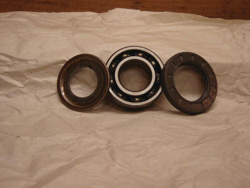
Recall that in my last update (November) I had removed the inner and outer bearings from the rear wheels. Those bearings were open, single-row ball bearings protected by separate grease seals. At least one had been making noise when the spindles were rotated and the grease on another was discolored, so I wanted to closely inspect them for signs of corrosion, wear or excessive heat. Beyond that, pressing them out had put force against their inner raceways which could have damaged or misaligned them.
But even after a thorough cleaning, the cages that retain the balls in their grooves blocked close inspection. Still, I was hesitant to just replace them. It wasn’t just a matter of cost. I was more concerned that any modern replacements I’d get would be of inferior quality. This is a dilemma I’ve faced before. Do you go with a perhaps slightly worn, but superior quality, older part or replace with a new, but potentially lower quality, piece?
The markings on the bearings indicated they were standard, thirdparty parts that are still available from the original manufacturer. That didn’t guarantee that their quality standards hadn’t fallen over the years, though. So I decided to wait until I took a look at the front bearings. If I decided to go with new, I’d want to order them all at once anyway. In the meantime, I did order replacement grease seals, which had to be replaced as normal wear items either way.
Pressing (and Pulling) Problems

I had removed the front end from the car as a unit. It’s a straightforward arrangement with a carrier going side-to-side and wheel hubs/spindles mounted via control arms and kingpins at either end. Up and down movement is regulated by coil springs over shock absorbers. A rack-and-pinion steering mechanism is attached to the front of the carrier, with tie rods connecting to the wheel hubs. As with everything else on the underside of the car, however, the whole assembly was covered in grease, grime and undercoating that would need to be removed before I could assess things. One thing was clear, though: to get it all apart, I’d have to free a bunch of rusty castellated nuts and cotter pins that were sure to give me trouble. So I cleaned them off and started soaking them in penetrant while I went ahead and removed the front brake drums to get a look at their bearings and see if the internal brake components were there this time.
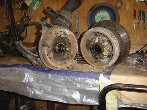
The front drums were pressed on with inner and outer bearings mounted in the drum. Extracting the drum meant pulling it off the spindle. But these drums are finned aluminum, so hammering from behind or pulling directly against them from the front was not the way to go, as evidenced by a number of chips and dents caused by some previous owner. Instead, I needed to pull out against the lug nut studs while pushing in against the end of the threaded spindle. For this, the NSU manual called for the use of yet another “special tool” that I didn’t have.
Doing the Brakes My Way
Once again, I had to come up with a way of getting the job done with whatever was at hand. I needed a plate to bolt to the wheel studs that I could pull against. It would need a hole in the middle to allow me to simultaneously push against the end of the spindle. It would have to be strong so it wouldn’t bend under the pressure. And it would need to be sized so I could use one of the several three-jawed pullers I’d accumulated over the years.
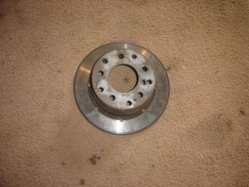
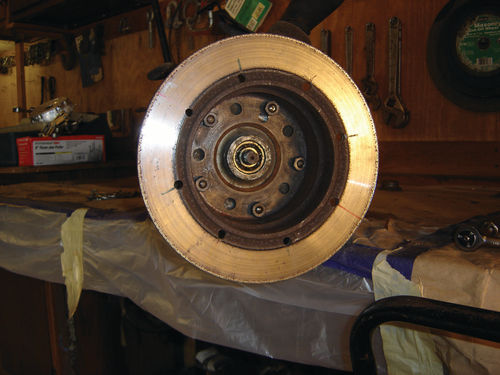
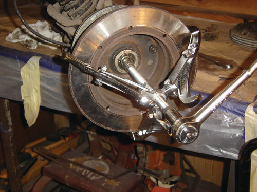
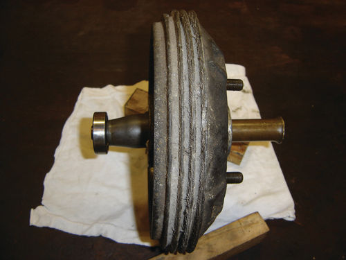
We’ve all heard of Murphy’s Law (“Whatever can go wrong, will”), but there seems to be a corollary: “None of the pullers you already have will fit the job you need to do.” (Another variation seems to be: “The part you need to clean will always be just too big to fit in your blasting cabinet”). In this instance, though, I’d defy Murphy by making the part to fit the puller, rather than finding another puller to fit the part. I looked around and found my answer in an old disk brake rotor I had from another car.
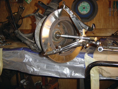
This rotor had a central hub that fit over the wheel studs on that other car. Those holes didn’t line up, so I had to drill new ones to fit the NSU. Then I mounted it backwards so the rotor stood out from the NSU brake drum. This allowed me to get my biggest puller in place and off came the NSU drums. One pleasant finding was that all the front brake components—shoes, springs, etc.—were there this time, unlike the surprise I encountered when I removed the rear drums and most of the internal components were missing. While the front brake parts will obviously need renewal or replacement, at least I can see how things should look and work.
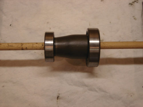
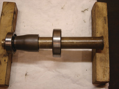
One drum came off with both its inner and outer bearings still in place. The other came off leaving its inner bearing pressed onto the spindle, but I was able to remove that with one of my other pullers. Looking inside the drum from that inner bearing opening, I found a curious tapered spacer was used between the larger inner and smaller outer bearings, surrounded by copious amounts of grease. It was sized to match the inner raceway diameters of the bearings at either end. That drum was easy to deal with. I lifted out the spacer, cleaned the grease and used my trusty, high-tech threaded rod/nuts/ washer arrangement to press the outer bearing from the drum. The other drum, however, presented something of a dilemma.
I now faced a drum with inner and outer bearings pressed into it with a conical spacer butted between the two inside the drum’s hub. This left no way to get a grip on either bearing from the inside to pull it out. Each bearing was pressed into the drum against a ridge or shoulder, so pushing from one side against the spacer to pop the bearing out on the other side wasn’t an option either. How the heck was I going to get these bearings out of the brake drum?
Closer examination of the first drum that was now bearing-free revealed that the spacer’s larger end was smaller than the hole for the outer bearing. That meant that if the spacer itself could be pushed against the outer bearing, both would push through that opening. But how was I going to push a conical spacer from its inside? I’m sure NSU had a special “conical pressing tool” to do the job which, again, I didn’t have.

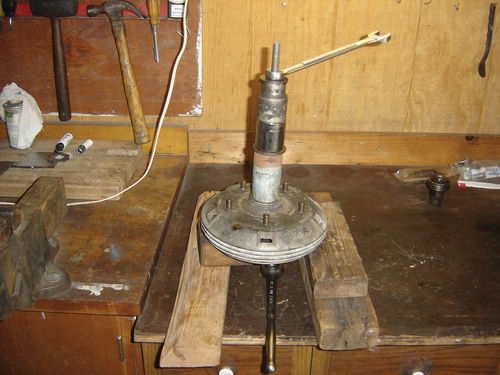
I first tried a piece of wood, hoping the outer bearing wasn’t held too firmly, but the wood just crushed. I needed something stronger but still soft enough so I could put the whole thing in my bench press and exert enough force without fear of mushrooming that spacer. In this case, luck was smiling on me. I have a bunch of brass drifts, one of which was pretty hefty but small enough to fit through the inner bearing hole into the spacer. What’s more, it was tapered.
While the taper didn’t match that of the spacer exactly, it worked. Under pressure, the spacer pushed the outer bearing from its hole and fell through with it, leaving only the need to once again employ my threaded rod/nuts/ washer arrangement to pull the inner bearing from the drum. After cleaning and examining the front bearings, I was still unsure of their condition so I decided to order a new set for the front and rear. I concluded the risk of failure from reusing the old ones outweighed the risk of inferior quality new ones.
In place of grease seals on the exposed sides of the front bearings, NSU had used a part called a Nilos ring, something new to me. These are essentially thin metal caps that fit tightly against the face of the bearing and are designed to wear against the bearing, creating a metal-to-metal seal. I suspect their use on the front and not the back had something to do with the fact that the front drums spin on bearings against a fixed spindle, while the rear drum turns in unison with the spindle against the bearings. Regardless, it’s recommended they be used only once and since they are still available from the bearing manufacturer I ordered them as well.
You Won’t Catch Me Singing “Welcome Back, Cotter”
I don’t know if there was a Mr. Cotter, or what evil inspiration might have led to the development of his cotter pins, but these things have been the bane of my existence as long as I’ve been working on cars. Their placement suggests the intent of serviceability (or else why not just weld the darned nut on?), but their construction ensures anything but. No wonder modern tie rods, etc. have gone to lock nuts instead.
As noted, the whole front end was held together with castellated nuts and cotter pins, very few of which came free. The ends of the pins usually broke off, leaving just enough sticking out to block the nut. Sometimes a very fine punch would drive the pin through. Most times it would just mushroom the end of the cotter pin into something akin to a rivet head. Then, very careful drilling with tiny, breakable bits was the only way to get the rest out. It was tedious and maddening, but eventually they were gone, allowing the front end to come apart, but with one precaution: I had to be careful in releasing the tension from those coil springs first, or they might become lethal projectiles.
Normally, spring compressors would be used, but I don’t have one of those either. Even if I did, these springs were small, tightly packed and buried behind other components so I doubt they could be gripped by a traditional tool anyway. An option would be to run a threaded rod down inside the spring after the shock is removed, with nuts behind large washers or plates at the ends to gradually release spring tension.
But, as in the rear, I couldn’t get the shocks out. The nuts at the top were again so rusted that the body of the shocks just turned with them and there was no way to get a grip on it through the side or the bottom of the spring. I got the bolts out of the bottom of the shocks, so the control arm they and the springs rested on could pivot down and away if I removed its mounting bolt. But, again, this had to be done while maintaining control of the spring. I’ve done this before when I had suspensions mounted in a car. I simply put a hydraulic jack under the bottom of the spring mounting point,
freed things up and slowly lowered the jack to release the spring. So, essentially, I needed a way to simulate having the suspension mounted in the car.
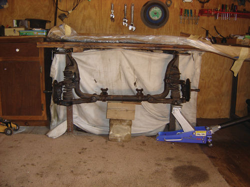
I found my answer in a heavy workbench in my barn. It had a steel frame with heavy timbers bolted to the top and the feet bolted to the floor. I was able to position the suspension underneath it and clamp it in place with enough clearance below. I put the jack under each side, compressed the spring a bit and removed the bolt from the control arm. Then I lowered the jack slowly, allowing the spring to expand gently.
Beating the Bushes for Bushings
I still need to address the tie rods, steering rack, kingpins and all the rubber bushings at various connection points in the front end. I’m hoping that, as with the bearings, some of the parts needed will be standard items that are still available. But I’m also checking with former NSU Club members to see if they know of crossreferences to parts used in other, more mainstream cars. Finally, I’ll be checking in to see if the body shell has advanced in the queue for stripping and priming.


