Restoring a 1976 Triumph Spitfire Part 3
It’s Time for the Suspension and Steering… Which Leads to Several Parts Problems.
At the end of Part 2 of the restoration of my 1976 Triumph 1500 (October), I was ready to start reassembly of the Spitfire’s front suspension.
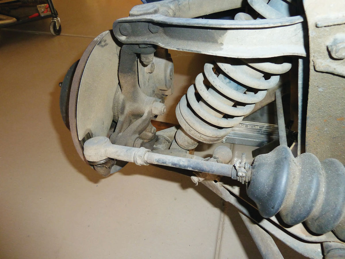
The front suspension of the Spitfire is simple in nature, consisting of unequal-length wishbones mounted to the chassis and connected to each other by the vertical link, which in turn provides the mounting for the stub axle, disc brake assemblies, and rack-and-pinion steering tie rod ends. Suspension damping is handled by a coil spring/shock absorber assembly mounted to the lower wishbone and the upper wishbone chassis mount.
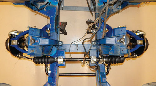
An idea of this arrangement can be seen in Photo 1 that shows the “before” condition of the Spitfire’s front suspension. After 20+ years of storage, all the rubber pieces, the gaiters, and seals and bushings were dry-rotted and disintegrating. I also decided to replace the upper ball joints and lower trunnions as their condition was unknown, and they were easy and relatively inexpensive to replace with the suspension disassembled.

Proceeding with the installation of the upper and lower wishbones, the first problem was encountered almost immediately. On inspection of the newly supplied right-hand trunnion, it was obvious that it was not suitable for use. Compared to its left-hand sibling that had been sourced from the UK, the right-hand trunnion, sourced from India, was dirty and the interior threads damaged (Photo 2). After some back-and-forth with the supplier, who ultimately refused reimbursement or to supply a free replacement, I ordered a new trunnion from another source. I was out the cost of a new trunnion and lost a week on my schedule.

I Don’t Think That Wishbone Assembly Is Quite Right…
With the arrival of the new right-hand trunnion, new hardware was used to attach the upper and lower wishbones to the chassis, followed by the ball joint, trunnions, vertical link and new stub axles (Photo 3).
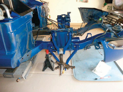
Finally, I was on a roll. Progress was easy and rapid. But that’s always a bad sign; at least for me.
I regarded the completed assemblies. Hmmm, aren’t the attachment brackets for the anti-sway bar supposed to be on the forward arm of the lower wishbone? Why yes, they are, and I have mounted each on the wrong side. (I have noted during the course of my lifetime that if there is a 50/50 chance of my getting something wrong, there is a 100% chance that I will.)
The workshop manual, probably assuming some minimum level of competence not possessed by me, did not address this and I missed it. Having by now become proficient in this operation, however, the wishbones were quickly reversed and order restored in the universe.
That Stub axle Just Won’t Work
The coil spring and shock assemblies were installed next without incident with new polyurethane bushings from TS Imported Automotive, and I proceeded with the installation of the front hubs.
Like the front hubs of many vehicles, the Spitfire’s hubs are a sub-assembly of their own, with inner and outer wheel bearings, grease seals, and the attached brake discs. Each of the hubs was cleaned and had new bearing races pressed in by a professional brake shop. I then repacked each hub and bearing with Sta-Lube Extreme Pressure Premium Red grease, installed new brake discs with fresh hardware, and slipped the completed hubs and bearings onto the stub axles.
And so the second major problem revealed itself. The front hub assembly of the Spitfire is held in place on the stub axle by a “D” washer secured by a castellated nut, which, after being torqued to the correct setting, is secured in place with a split pin. The correct torque for the castellated nut is 5 ft.- lbs., and is supposed to result in an end float of .002” to .005”.
On both of the hub installations the nuts were torqued to as much as 15 ft.- lbs. and I was still seeing end floats in the range of .012” to .015”.
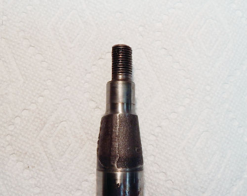
Both hubs were removed and close inspection of the stub axles eventually revealed the problem. The threaded portion of the stub axle is supposed to have a flat area machined along its length to the shoulder of the first bearing surface to fit the “D” washer. I have included a photo of the original axle stub that, if you look closely at the lower portion of the threads, shows how the axle should be machined (Photo 4). The “new” stub axles did not have the flat portion machined all the way to the shoulder and so the “D” washer would not seat fully against the bearing surface shoulder, resulting in excessive end float. So off came the hubs and out came the newly installed stub axles, followed by an earnest conversation with the supplier. In this case, I was given credit for the returned axles, and a new set of stub axles sourced from yet another supplier were fitted with no subsequent hub end float problems. A tentative sense of optimism returned.
That Hub Bearing Isn’t Smooth Enough
Alas, that optimism was premature. After installation, each hub was spun by hand to check for disc run-out and smooth operation of the bearings. The right-hand hub was fine. The left-hand hub was…noisy, at least more so than the right-hand side.
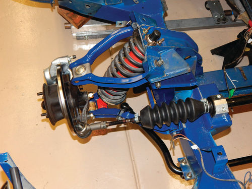
How much bearing noise is too much I really don’t know, but since I felt, or at least imagined, a slight roughness also, I decided to replace the left hub bearings. So new bearings were ordered and the offending hub returned to the brake shop to have the new races installed yet again. The hub was re-installed and was much quieter and smoother. With the hub installation now complete, I mounted the rebuilt disc brake calipers (Photo 5) as a way to conserve precious shelf space, but the Spitfire’s brake system will not be fully repaired until the rear suspension is rebuilt.

Turning to the Steering and Anti-Roll Bar
Fortunately, I was able to take advantage of the waiting time for the parts and necessary rework of the hub to complete tasks on the Spitfire’s rack-and-pinion steering unit and antiroll bar. Each of these components had been removed when the front suspension was disassembled, and the wait time provided the opportunity to work on them.
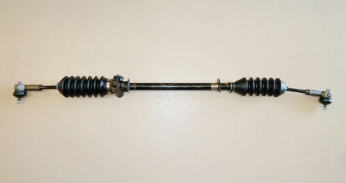
The rack-and-pinion steering was checked for excessive wear, and, finding it within specifications, I decided to reuse it rather than replace it.
After cleaning the steering unit, new grease-packed gaiters and tie rod ends were installed (Photo 6).
The anti-roll bar was cleaned of surface rust with a bench-mounted wire wheel, and then given three coats of Rust-Oleum semi-gloss black paint.
Once the paint had dried, new end links were fitted to the anti-roll bar, and my daughter Erica helped to install both the steering rack and anti-roll bar (Photo 7). The rack-and-pinion installation benefited from an upgraded aluminum steering rack mounting kit from The Roadster Factory, and the anti-roll bar was fitted with new polyurethane mount bushings. Only an approximate steering alignment was done at this time, basically by eyeballing the wheel alignment with the steering wheel straight ahead. The final alignment will be done once the Spitfire’s engine has been re-installed, as this is necessary for it to be done correctly.
The front suspension rebuild is now complete (Photo 8). It certainly looks much better than the starting point and will undoubtedly give much improved handling over the stock setup. (Take another look at Photo 1 for a comparison.)
Pleased, So Far, With a New Parts Source
During this session, I experienced delays and additional expense due to defective or substandard parts that originated from “low cost” manufacturing sources, a theme that has been noted in many AR articles. I have identified a supplier, SpitBits of Lincoln, California, that has, so far, provided excellent parts at modestly higher prices; prices that I am more than willing to pay. I will let you know if this continues to be the case.
In part 4, I will start the disassembly and rebuild of the Spitfire’s rear suspension and brakes.
Resources
SpitBits P.O. Box 281 Lincoln, CA 95648 Sales: Customer Service/Technical Support: spitbits.com
TS Imported Automotive 108 South Jefferson St. Pandora, OH 45877 (Tech/General Information) tsimportedautomotive.com
The Roadster Factory PO Box 332 Armagh, PA 15920 Customer Service: the-roadster-factory.com


