
Repairing a GM Scissor Top
This Uncommon System Can Prove to Be a Problem for Convertible Owners. Here’s How to Diagnose and Repair One for Top-Down Driving.
IN THE EYES of restoration enthusiasts the past several decades have brought some not-so-desirable mechanical designs. The GM scissor convertible top used on full-size cars from 1971 to 1976 seems to fall into this category. These uncommon tops are known to be finicky more often than not… However, with some inspection and easily accessible new parts, you can get yours operating smoothly again with a day of work.
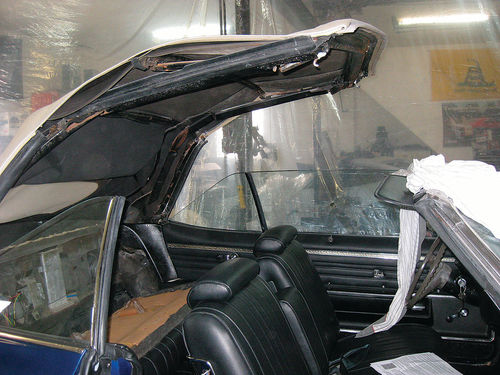
Until the introduction of this Hideaway or Scissor top, most traditional convertible tops would fold straight back in an accordion style over themselves and would lay above the body of the car causing the boot to stick up significantly from the rest of the body line. In an attempt to provide a cleaner appearance and, more importantly, allow for a wider back seat area, GM redesigned the top assembly in a manner that allows the side rails to fold in instead of back and the top to drop into a well behind the rear seat where it can be hidden by the boot without sitting way above the rear deck of the car. As the side rails collapse inward toward the center of the car the left and right sides cross in a shearing motion, mimicking a pair of scissors.
We’ll Start With the Switch
These tops are electric and contain a number of moving parts that must all work in their proper sequence for the top to open and close correctly. The electrical system consists of a switch, a relay, and a small top motor that resembles a power window motor. If your top is completely inoperable this is where you would want to start your diagnosis.
The particular vehicle in this article is a 1971 Oldsmobile Delta 88 and there were several factors causing its top to not operate properly. First and foremost was a broken electrical switch for the top. The original plastic switch had broken at some point and was unrepairable. Unfortunately, the switch used in this car was a one-year-only design and I was unable to track down an original unit. Instead I was able to purchase an acceptable looking double-pull, double-throw switch from the local electronics store and modify the original switch housing to accept this switch and still look good. Then it was just a matter of removing the old connector and wiring up the three wires to the new switch.
Power from the battery goes to the middle of the switch and each of the other wires goes onto opposite ends of the switch for up and down movement. If you aren’t sure whether or not your switch works you can test it either in or out of the vehicle. In the car you first want to probe the orange wire with a test light...you should have a constant 12V. Then as you operate the switch in either direction you should have 12V at either the gray or purple wire, but not both simultaneously. If you do not have these 12V readings at the gray or purple wires, but have it at the orange, your switch is bad. A lack of constant 12V at the orange wire indicates a wiring issue between the battery and switch. You can also disconnect the three-wire connector at the relay behind the rear seat and probe there... this will help verify if the wiring from the front to the back of the car is good. Finally, to test the switch outside the car, simply hook up a continuity tester between the power lead on the switch to each of the outside connections. As you operate the switch in each direction you should have continuity to each respectively.
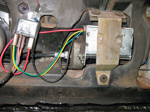
Testing the Top Relay
The next step is verifying the correct operation of the top relay. As mentioned earlier, it is generally located behind the rear seatback. Testing the relay in the car once the switch has tested “good” is very simple. With all of the wiring connected properly and the key in the ON position you first want to test for constant 12V at the orange terminal in the middle of the relay. Next push the top switch in one direction and check for current to the yellow and red terminals. Finally push the top switch in the other direction and look for current at both the green and red terminals. If all of these readings check out, the relay is good.... if not, you can do a bench test.
To bench test the relay, attach a constant 12V to the center relay terminal (orange) and a grounded test light to the output terminal (red). Now with a second 12V lead apply power to the yellow/purple terminal while applying a second ground to the green/gray terminal. The test light should light up and you should hear an audible click. Now,if you swap the second 12V lead to the green/gray terminal and the second ground to the yellow/purple terminal the test light should once again light up and produce an audible click from the relay. If you do not get the test light to light up in either of these tests replace the relay.

Let’s Check Out the Motor
This leaves us with the motor as the final piece of the top operation electrical system to consider. If the switch and relay have tested out OK and there is battery power, the motor should be suspect.
Before applying power to the system for your test, disconnect both top cables from the motor…they screw on just like a speedometer cable would. By disconnecting them it alleviates any binding in the mechanical system which could skew your test results. With the cables disconnected, make sure the black motor wire is properly grounded to the body of the car and try the top.
If the motor fails to operate it should be repaired or replaced. Be sure to remove and inspect the motor drive gears and housing. The gears are plastic and could be broken or severely worn from years of use. They are available separately from the motor if you need them. If not, clean and grease them and you’re good to reinstall.
Now for a Mechanical Inspection
If your top is still inoperable or extremely slow after squaring away the electrical system, you must now look into the mechanical side of the action. A number of items can affect the top’s performance including friction, broken drive cables, bent or worn side rails or side gears, worn #2 bow side brackets, or broken side hold-down cables.
Broken drive cables are the easiest to check. As mentioned earlier, they are basically the same as a speedometer cable and can be unscrewed from the motor and side gear assemblies easily. Remove them and check to make sure they turn freely with no binding. A certain sign of a bad or loose drive cable would be when one side of the top attempts to go up or down while the other remains stationary.
The #2 bow side brackets can be checked by looking for play where the pivot ball attaches to the bracket. Look for breaks or extreme play in the pivot assembly. The side hold-down cables are the last visual inspection. They run up the side of the top and help hold the top in place when it’s up. Each side cable has a 2" shunt cable that is attached to the #2 bow. Make sure it’s not broken or disconnected. If so, replace the cables or if the screws securing the cable will no longer hold in the #2 bow, replace the bow.
The next part of the system you will want to check are the side rails. To do this, you want to open the top so that it is approximately 2' back from the top of the windshield. Then, grab the front of one of the side rails and move it up and down. You should have less than 2" of total play. If you have more than that, the side rail on that particular side is bad…either a bent rail or too much play in the pivot joint at the center of the side rail. New or rebuilt side rails are available from a number of suppliers.
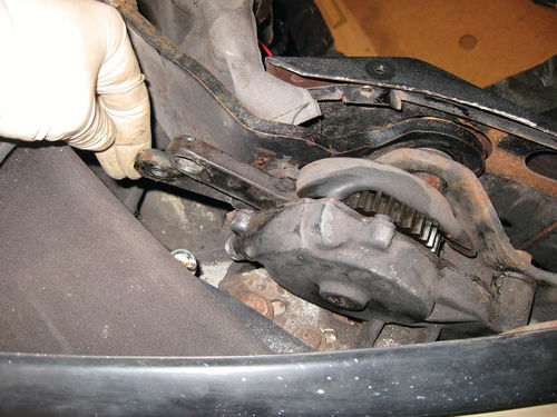
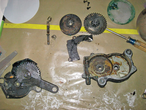
The side gear assemblies are the final mechanical part of the scissor top system to be checked. There is one on each side and they actuate the movement of the top between the cables and the top frame. To test the gear assemblies, fold the top all the way down and disconnect each drive cable from its respective gear assembly. Now, grab each of the arms coming out of the assembly housings and force it through its full range of motion. You should have even resistance throughout the entire range with no binding and no loose spots. This turned out to be the problem for the Delta 88 being diagnosed in this particular case. The gear assemblies had some spots where it was extremely difficult to move the arms at all. You can purchase rebuilt gear assemblies, however I decided to explore further and see if I could free up these originals.

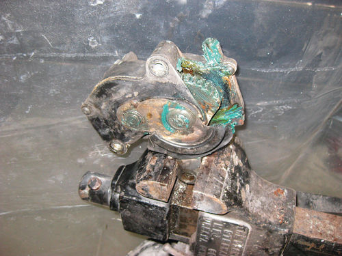
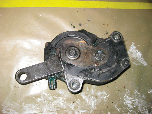
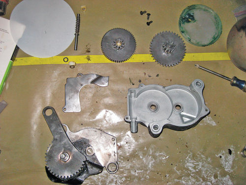
Remove the mounting bolts that hold the gear box in the car and then on the bench you can remove the screws that hold the case together. After opening up the case I found a lot of original grease that had basically solidified inside. I also did a visual inspection of all of the gear teeth and the worm gear inside and found no signs of excessive wear or broken teeth. At this point, I pulled the entire assembly apart and degreased the gears. I followed that up with a good shot in the blasting cabinet for all of the pieces to remove the solidified grease as well.
Once everything was cleaned up, I reassembled the gear assemblies using fresh bearing grease on all of the mesh surfaces and retested the movement of the external arm with the gear box mounted lightly in a vise. At this point both gear assemblies were moving smoothly throughout the entire range of motion. Next they were bolted back into the car.
Before attaching the arms back to the top frame and the drive cables back onto the gear boxes be sure that you have the arms in the same position so that the top will raise and lower evenly. Once you are sure of that, connect everything back up.
After buttoning the left and right assemblies back up, I hooked the battery up in the vehicle and tested the top assembly again. At this point everything was working smoothly and this Oldsmobile was ready for top-down driving once again.


