
Building a Center Console
Readers Have Asked for More On the Console In Project ’46. Here’s How to Build One for Your Own Ride.
THE MOST IMPORTANT thing to understand about the construction of the console in Project ’46 is that I built the unit in place in the car.
Why did I build the console in this uncommon manner?
Back in the planning stage of the project I knew I would end up with a thick bundle of electrical wires leading to the rear of the car—and the car doesn’t have hollow rocker panels or recessed floor pans to provide a place to route wires. So when you are making modifications, such as switching the doors to a suicide opening, it forces the routing of the wires going to the power windows, power door latch activators, and dome light switches to move rearward. The best location for getting all those wires to the rear is to run them right down the middle of the car.
Console Construction
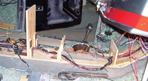
The first step was to install the shifter mounting plate then carpet the drive shaft tunnel. There is no padding under this carpet as padding would interfere with the stability of the console. I just glued the carpet into place on the tunnel using 3M #8064 Vinyl Trim Adhesive and allowed the carpet to overlap down onto the floor pan an inch or so (Photo 1).
If you look closely you can see the shifter mounting plate near the far right center of the photo just across from the emergency brake lever. The shifter mounting plate is a three-inch elevated steel platform that has been welded to the floor pan. I elevated the platform to make reaching the shifter a little easier. The carpet has been cut and trimmed around this platform.
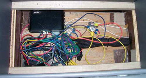
The big thing to notice in Photo 1 is the wiring harness going to the rear of the car. You guessed it. This bundle is about an inch thick. It contains the above-mentioned wiring plus wiring for the tail lights, rear license plate compartment door, trunk light, fuel pump and speakers. What’s the cluster of loose wires all about? This cluster represents the terminal points for many of the wires going into the doors and will eventually be situated in a hidden compartment at the bottom of a console storage compartment located between the two front seats.
This compartment will have a removable bottom that will allow me access to the wires. What isn’t shown in the photo is that this cluster of wires will eventually be connected to a remote control receiver for the door latch activators, circuit breakers to provide protection to the power windows, and even a remotely located trunk latch release button. I opted to place these components in the console for the sole reason that they would be easy to access should the need ever arise.
In Photo 2 I’ve laid out the bare bones of the console. Yes, most of the wood used here is recycled…I do what I can. The main part of the base was cut from a single piece of 3/4-inch-thick plywood and measures nine inches wide by 65 inches long. Notice the short section of additional base that angles up the firewall. This section is nine inches wide and 12 inches long. Both pieces are secured to the floor pan using #8 x 11 ⁄2-inch sheet metal screws.

Before screwing the main base panel into place on the tunnel, I cut a hole in the plywood for the shifter platform. Be sure to note that the hole I cut for the shifter platform is four inches longer than the platform itself, with the excess space located forward of the platform. That gives me room to bring the shifter cable up through the drive shaft tunnel and connect it to the front of the shifter.
What did I do for a shifter? I used a complete shifter assembly from a late ’80s Camaro. I wanted a shifter with a parking lock and a neutral safety switch. The Camaro shifter provided both, a pushbutton lock on the side of the “T” shift handle, and a factory-type neutral safety switch that allows the car to be started only in park or neutral.
Of course, I can’t just let well enough be well enough. I eventually shortened the shifter handle by an inch. Why shorten the handle? I have a pair of cup holders located just aft of the shifter and a CD player located just forward of the shifter. A short shifter will keep it out of the way no matter what position it’s in, be it park, reverse, neutral or drive.
Next I routed my wiring bundle along the length of the console base. Here’s a good tip: Once the console is finished, there will be no going back and adding wires. With that thought in mind I added three extra wires going from the fuse block under the dash to the rear of the car. Two of those wires are powered only when the key is ON, the other one is connected to full battery power at all times. All three of these wires are capped individually with blue butt connectors and taped to the wiring harness. It’s not a good ideal to leave live wires laying loose anywhere in your ride.
The uprights visible in Photo 2 are also made of 3/4-inch thick plywood and all three have a “U” cut out on the bottom. This facilitates routing the wire bundle through the console.
The forward-most upright measures four inches tall, the second one is also four inches tall, and the third upright is 15 inches tall. The uprights are glued and stapled to the base panel. The staples are 11 ⁄2 inches long. Don’t have a staple gun? Your woodworking buddy down the street probably does and he’d love to see what you are doing.
Notice the additional bracing glued and stapled to the uprights. This helps support and stabilize the uprights as well as provides support points for the top structural surfaces of the console. You can get a better idea of how this works in Photo 3. This is the rear section of the console with the top structural surfaces glued and stapled into place.
Take a close look at this section and you can see the two round holes at the center of the photo. These eventually will become cup holders. You also can see in the lower right corner where I mounted two circuit breakers to the base panel. This part of the console will house the storage compartment with the false bottom I talked about earlier.
About Those In the Back Seat…
Here is how the back half of the console will be constructed.
The box portion at the rear of the console is 15 inches tall, 18 inches long, and five inches wide, roughly half as wide as the front section.
This rear section will serve as a center armrest for the rear passengers and will not open for storage. The forward half of the rear section is five inches tall, 16 inches long, and five inches wide. As noted, I cut two 31 ⁄2-inch diameter holes in the top structural panel of this section to serve as cup holders.
Look closely at Photo 3 and notice that the base of the rear section is stepped up where the floor pan steps up. Also notice that I added an additional upright that is only 10 inches tall to the front of the rear section then angled the top panel back to meet the taller rear section. That angled section improves the looks of the console as well as serves as a location for installing a power outlet. DTVs, (digital television), video games, etc. need power and adding an outlet here will provide that power.
Going Up Front Again
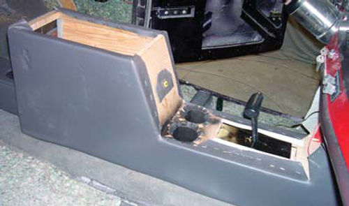
Shifting focus once more to the front half of the console, I have a lot of things going on in Photo 4.
Let’s start at the front and work back. The five-inch tall uprights are topped with a 1/4-inch-thick sheet of plywood. This piece is structural so it is glued and stapled into place. Also notice that I cut a 11 ⁄2-inch wide by 5-inch long slot for the shifter and added two 31 ⁄2-inch diameter cup holders to the panel.
Working farther back I added an additional 1/4-inch-thick plywood face to the first 15-inch-tall upright and leaned it back. How did I do that? After installing the top panel on the lower front section, where the cup holders are located, I added a one-inch wide spacer (square block of wood nine inches long) on top of the top panel where this panel meets the first 15-inch tall upright. The new face gets stapled to the block and to the top of the upright for an instant lean of one inch, or about 10 degrees.
While we’re at the first 15-inch-tall upright, take note of the trunk release button centered on the face panel. This yellow button has a picture of an open deck lid stamped on it to let you know what the button does. Where’d I get it? Many GM products have this button hidden in the glove compartment. This one came from a salvaged Oldsmobile.
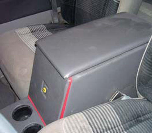
Something you might be wondering about is why the trunk release button is already mounted and why it is already trimmed out with the light gray vinyl. Take a look at Photo 5. Notice that the trunk release button is recessed into a square opening cut into the trimmed-out face panel. Having the button recessed reduces the chances of someone accidentally bumping the button and opening the trunk.

Working now on the console storage compartment, I started by framing the top of this compartment using 1-inch by 1-inch square lengths of oak. I need the top of this compartment framed in some pretty stout wood in order to provide solid mounting locations for the hinges and latch for the top panel.
Referring back to Photo 4, notice that the sides of the front half of the console have now been covered with vinyl. This is the same light gray vinyl I used to make the project’s door and quarter panel trim panels.
To cover the sides I started by laying out a cardboard template of the right side. I then used this template to draw out and cut two identical side panels from 1/4-inch thick plywood.
These panels were padded using the same 1/8-inch thick foam padding I used on the door and quarter trim panels, then covered with the light gray vinyl. Be sure to notice that I gave the top edges of the side panels a couple of extra inches of vinyl, which I then glued and stapled to the console framework.
How did I attach the finished side panels to the console? Heavy duty construction adhesive purchased at my local home improvement center.
You might notice the clamp tracks near the top rear of the center storage compartment. A scrap piece of plywood under the clamp would have prevented this temporary problem.
The top of the storage compartment is constructed from a piece of 1/2-inch thick plywood. I needed a surface that would be thick enough to accept and hold the hinge screws, yet still be light enough to be easily lifted.
I also used two separate hinges to hinge the lid. If I had this to do over I would have gone with a piano-style hinge if for no other reason than the piano hinge is a little stiffer and would offer a little more stability.
To cover the lid I started by adding two layers of 1/4-inch-thick foam, the same closed cell foam I used when constructing the interior of the car, to the top of the lid then covered that with the light gray vinyl. This gave me a soft but firm lid that also serves as an armrest. Thus the reason for making this compartment 15 inches tall.
Notice in Photo 6 that I added a vinyl covered piece of 3/16-inch-thick Luan plywood to the underside of the lid. I also used the Luan plywood to trim out the inside of the storage compartment and to make the false bottom for the compartment.
Be sure to notice the catch strap I added to the lid.
I don’t want the lid to fold completely over backward. That would stress the hinges and eventually result in the attachment screws pulling out.
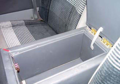
Here is a shot of my hidden section under the storage compartment (Photo 7). This is where that bundle of loose wires visible in Photo 1 ended up. Once the removable false bottom is added to the compartment, nobody will see this tangle of wires.
Now let’s shift our focus to the very front of the forward section. Notice up here that the sides of the console extend up until they disappear under the dash (Photo 8). This section of the dash is also framed with 1-inch by 1-inch square lengths of Oak to give it strength. I cut a face panel from 1/4-inch-thick plywood to house the CD player, plus another power outlet, and covered that panel with more of the light gray vinyl.
Be sure to note that the face of this section leans toward the firewall. That lean is 20 degrees and is there to improve upon the looks of this section. The lean also helps make the face of the CD player a little easier to read from the driver’s seat. What’s the black thing on the side of this section? An MP3 plug.
A tip: When constructing this section of the console, you must leave adequate room both above and behind this compartment so that you can reach inside to attach the support bracket that holds the CD player in place. This bracket will come with your CD player.
Return To the Back Once More
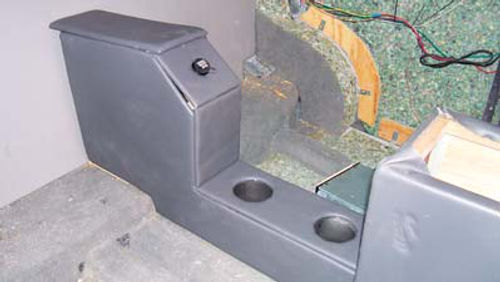
Turning once again to the rear half of the console you can see in Photo 9 that I’ve covered the sides of this portion the same way I covered the sides of the front section, by making templates, cutting the side panels from 1/4-inch thick plywood, then covering those with foam and vinyl.
The top panels visible in Photo 9 are made the same way the side panels were made with the exception of the rearmost top panel. This portion of the console will serve as an armrest for the rear seat passengers and needs a little more padding than the other panels. To do that, I doubled the foam to make this panel softer.
Something not obvious here is that the top panels have not been attached. At this point they have just been laid in place to be sure they fit. Before I make them a permanent part of the console by gluing them down using construction adhesive I’ll dress up the borders of the pieces with a red accent.
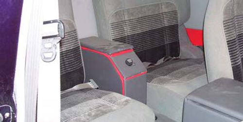
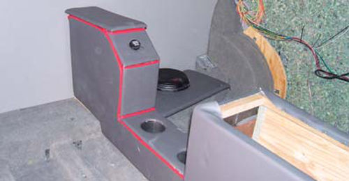
To make the accent pieces I cut several two-inch-wide strips of the same red vinyl I used to accent the doors and quarter panel trim. I then wrapped and glued those strips around a length of 5/16-inch diameter cotton cord to make a form of welting. This welting is stapled into place and goes around all of the top panels previously covered with the light gray vinyl (Photo 10).
Some Finishing Touches
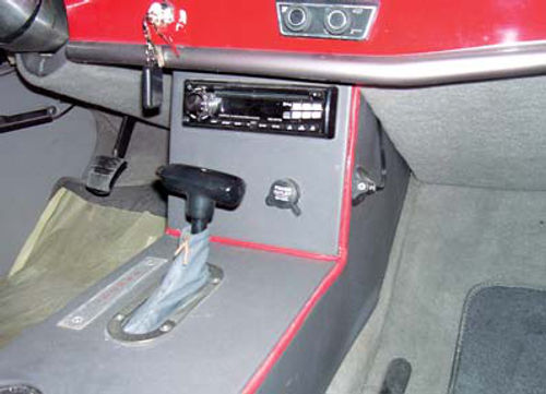
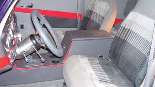
These extra touches start with the shifter. Notice in Photo 11 that I added a light gray leather boot to the shifter. I thought a leather boot would look a lot nicer than a black rubber boot. The chrome trim ring is from an after market emergency brake lever I had stashed in the shop from a previous job.
To the left of the shifter is a PRNDLL, pronounced “pernandal” by some and “prindle” by others. This is an aluminum plate stenciled with the pernandal/ prindle letters then clear coated. Two screws hold it in place.
Forward of the shifter is the CD player and power outlet. Did I mention the power outlets, this one and the one in the rear, were removed from a salvaged Dodge minivan? They were.
The cup holders, both front and rear, were first lined with black painted sheets of plastic.
What type of sheeting is best? For heavy plastic sheeting try a “For Sale” sign from the local mega mart.
Once lined, the cup holders were finished by adding inserts from a couple of salvaged Ford Explorers.
Next time I’ll move on to bigger things. Got a question? Send it along.
Editor’s note: If you missed Larry’s series on modifying his ’46 Ford Business Coupe or would just like to have it in book form, “Project Street Rod” is now available for $24.95 by calling .
Project car provided by:
LPL Body Works, LLC
5815 Contented Lane
Amarillo, TX 79109
Paint and body repair DVDs


