
Brazing, Soldering and Riveting, Pt. 2
We’ll Start With Custom Lead Work and Then Lead-Free Solder. After That, We’ll Turn to Some Riveting Projects.
EDITOR’S NOTE: LAST month we gave some examples of metal brazing and began our discussion of soldering. Now it’s time to resume our look at soldering before we move on to some work with riveting.
Lead Sleds
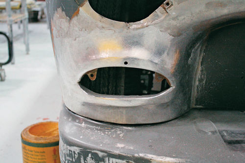
Lead is most often used in restoration to replicate factory surface treatments in areas subject to high stress or vibration, but decades ago it was used as a sculpting medium by car customizers like Bill Hines. A previous owner of our 1950 Mercury began customizing it but lost interest. The car began life as a coupe, but at some point was made into a convertible. Someone also learned to weld on it—sort of. One of the eternal truths of automotive restoration is that inherited problems from previous restorers are always worse than problems that occur naturally. The Mercury has proven the validity of that statement many times over. Anyway, it is our project now, and we are determined to see it through to completion. One area that needed attention was the sheet metal around the front turn signals, which are from a 1955 Chevy. Rather than cut out and attempt to fabricate new sheet metal to improve the transition to the light openings, we smoothed the area as customizers of the 1950s would have, with lead solder. As we added more and more lead to the low area surrounding the first turn signal opening, it occurred to us just how fitting the term lead sled is for an old custom such as this.
Lead-Free Solder
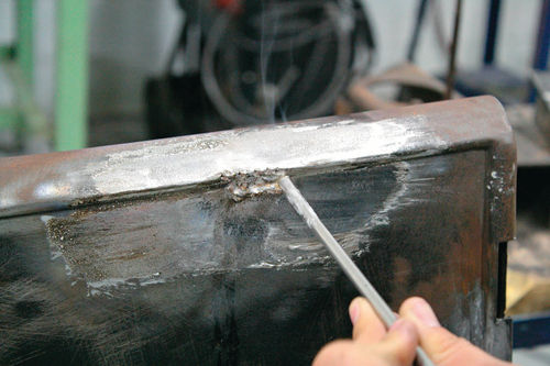
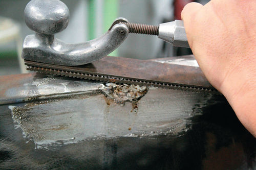
After completing the lead repair on (last month’s) demonstration piece, a Ford Model T door, I was anxious to compare one of the modern lead-free solders with traditional body solder. I prepared a second area on the Ford Model T door and repaired it with a well-known lead-free solder, an alloy of tin, copper, and zinc. Following the instructions I found on the company’s web site, I applied the necessary flux, heated it until it turned brown, and then wiped it as one would do with Tinning Butter. The lead-free solder goes onto the panel very much like traditional solder, though its consistency feels waxier than lead, which is not a criticism, just an observation. The temperature working range of lead-free solder is 100 to 200 degrees higher than the range of lead, so take this into account if you anticipate working on or alongside panels without much crown. We pushed the hot lead-free solder into position using a maple paddle and allowed it to cool. Filing the lead-free solder was infinitely easier than filing lead; it was more like filing a bar of soap. Lead is remarkably dense, of course, so every time you file it you are reminded that ease of finishing is certainly one of the reasons why plastic filler came into being. Lead-free solder files more like plastic filler, but it does not feather out at its edges as well as plastic or lead, in my opinion.
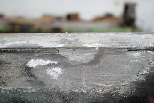
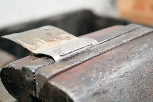
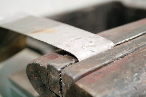
Based on the grandiose claims made about this product in the sales literature—superior strength, greater safety over lead, feather-edge capabilities— and its hefty price tag, I had high expectations for its performance. Inspired by T. N. Cowan’s hilarious plastic filler versus lead solder tests in his book “Automotive Body Solder,” I decided to conduct my own destructive tests to determine how well lead-free solder compares with lead. I applied lead solder and lead-free solder to two separate strips of mild steel and hammered them over in a vise. The pictures confirm lead’s superior flexibility. Overall I must say that I am not impressed by my first experience with lead-free solder. It must be worked at a higher temperature than does lead, which may lead to distortion, it will not move with the panel like lead does, it does not finish out as well as lead does, and its greater safety is only relative to lead. Do not apply lead-free solder and expect to be able to sand it as you would plastic filler. Read the OSHA material safety data sheets that must be made available for these products—these sheets will not be sent with the product, but vendors will have them available through their web sites. Heating and sanding these products releases metal fumes and metal dust, so do not be lulled into a false sense of security. Zinc, copper, and tin may not be as toxic as lead, but you should respect them nevertheless. Take the same precautions that you would when working with lead.
Riveting
Often an automobile restorer is called upon to replicate historic manufacturing methods for the sake of authenticity. Rivets, for example, have a certain look that is hard to simulate. Although rivets have not to my knowledge been used regularly on production cars for decades, they were commonly used before World War II, so restorers of older cars should develop some familiarity with them.
Solid rivets, as opposed to pop rivets, consist of a shaft, a manufactured head, and a shop head that is formed on the opposite end of the shaft from the manufactured head when the rivet is installed. Rivets are sized according to their shaft diameter and length. Rivets are typically secured using a rivet set, a steel tool that has a deep hole in its end for drawing the rivet down tight against the material it is intended to secure, and a shallow depression for forming the shop head after the rivet is set. The shallow depression is also handy for supporting the manufactured head while the opposite end of the rivet is being hammered. A hole through the side of the rivet set is there to evacuate small plugs created by punching rivets through very thin materials without pre-drilling holes. Because rivet sets typically work for only one size of rivet, you no doubt will find one day that you need to set a rivet for which you do not have the appropriate set. A lead block works quite well as a makeshift rivet set insofar as it can be used to support the manufactured head of a round head rivet while the opposite end of the rivet is being flattened. Once the lead block gets pockmarked, melt it to reestablish a clean flat surface. In a pinch, you can also drill a depression of the appropriate size in a hunk of steel or into a steel workbench top to support the manufactured head of a rivet as you set it. A homemade tool will need to be hand-held to put a shop head on, however. A few decimal drill bits near the sizes of rivets you’ll use most are indispensable for fine-tuning holes and removing damaged rivets.
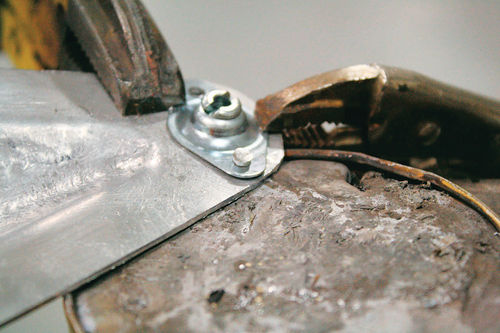
Try to match your rivet material to the material being riveted to avoid dissimilar metal corrosion (galvanic action). The general rule for selecting rivets is to use a rivet with a diameter equal to 2½ to 3 times the thickness of the metal through which it is driven. For riveting through two pieces of 20-gauge steel, for example, you would choose a 0.0910-inch-diameter rivet (0.036 × 2.5 = 0.090). With an automotive restoration project, hopefully you’ll have some samples of the original rivets to copy. When you don’t have anything to use for reference, follow the general rule and make sure the rivet looks right. Typically, old cars look quaint and, frankly, old, but not medieval. You want your project to look like an old car, not a portcullis, so avoid oversized rivets. Apart from the appearance, the rivet size matters because the increased force required to set larger rivets easily distorts thin sheet metal around the head, so that the riveted panel ends up wavy. Undersized rivets might not have the strength you need. The hole you drill or punch for your rivets should be 0.002- or 0.003-inch larger than the rivet diameter to allow you to insert the rivets fully without undue effort, but not so large that the rivets bend sideways or fail to hold the material securely. Make sure that enough of the rivet shaft protrudes on the back side of your panel to allow you to set the rivet firmly. Shoot for an excess length roughly equal to 1½ times the rivet’s shaft diameter. I will be the first to admit that this is a hassle to measure. Most people can estimate by eye and get it pretty close if they have an assortment of rivets already in hand. If you are ordering rivets, calculate the total thickness of the metal being riveted plus 1½ times the rivet shaft diameter. In real-life wrestling with old cars, you’ll typically be faced with the need to trim down rivets to get the correct length. An easy way to do this is to grip the shaft of the rivet with Vise-Grip pliers situated under the manufactured head and grind away the extra material on a bench grinder or belt sander. Try to leave the new surface as flat and burr-free as possible. Keep Vise-Grips of several sizes around for this procedure. Once you’ve identified the perfect width of Vise-Grip jaw for a specific project, this otherwise extraordinarily tedious job will be less painful. I usually grind several rivets, let them cool, and then quickly take off any burrs with a swipe of a file if needed. If the shaft is not ground enough and ends up too long, it will probably bend to the side when you try to set it.
Regarding the number of rivets and spacing between them, do some research on your particular project. If you have what you believe to be original panels, I would trust them more than just about any other source. Perhaps because of the level of minutiae involved, maniacal, self-proclaimed experts might lead you astray if given the opportunity to expound on rivet placement. The practical considerations are that the rivets are far enough from the edge of a panel that they can’t pull out or cause the edge of the panel to flare up and that they are close enough together to secure the pieces in question. Leave yourself a good space cushion of at least ¼-inch from any edge. Space your rivets apart a distance equal to at least three times the rivet shaft diameter or they will get in the way of one another when you’re trying to set them.
When riveting two things together, I find it helpful to drill each hole and secure the pieces with sheet metal screws or Cleco temporary fasteners to maintain perfect alignment at all times. If burrs are left from drilling, grind them off or the rivet will not sit flush against the metal. To set a rivet correctly, drill or punch a hole, insert the rivet, and situate the rivet set on the back side of the rivet with the hole over the end of the rivet shaft. Hammer the set to squeeze the sheet metal down against the manufactured head. With the manufactured head well supported, hammer the end of the rivet shaft to flatten it. Put the cup-shaped portion of the rivet set in place over the freshly flattened end of the rivet, and smack the rivet set to create the shop head. Steel rivets can be a bear to set by hand, especially as they increase in size. The ideal setup is to have the rivet through the material before you heat the end red hot before setting. If accessibility is an issue, it is possible, with an assistant’s help, to grip the manufactured head with a pair of Vise-Grips, heat the rivet shaft until it’s red hot, then push it through its intended hole, support the manufactured head against the cupped depression in a rivet set, and smack the opposite end of the rivet’s shaft with a hammer. Form the shop head with a second rivet set.
If you make a mistake in setting and you need to remove a rivet, grind the head enough to create a flat spot to facilitate center punching, center punch the rivet, and drill it out with a drill bit that is slightly smaller than the rivet diameter. I prefer to grind the rivet head very thin with a pneumatic cut-off tool and pop the rivet out with a punch. You can shear off whatever is left of the head with a cold chisel instead, but that method is more likely to distort the hole and scar the panel surface.
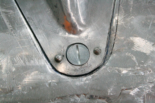
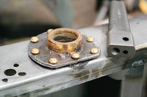
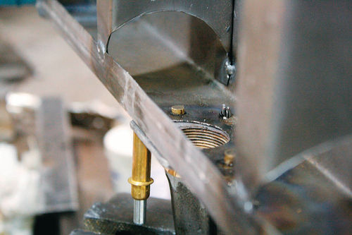
We used aluminum rivets to attach Dzus quarter-turn fasteners to the cockpit of our miniature streamliner. There is a special tool for dimpling sheet metal to receive a Dzus fastener plate, but we improvised with a small ball-peen hammer struck over the open end of a socket with a mallet. Without the indentation, the top layer of sheet metal will not sit flush with the bottom layer despite the offset flange. Our rivets were the common rivet alloy 2117T4, which is harder than the other common 1100F rivet, which is basically pure aluminum. Either alloy would have worked fine in this case because we chose our rivet for purely cosmetic reasons from rivets we had on hand. If we need to exceed 200 miles per hour in our streamliner, at least we’ll have the peace of mind knowing that we chose the tougher alloy. To learn everything you could ever want to know about rivets, consult Nick Bonacci’s “Aircraft Sheet Metal.”
Editor’s note: This section is excerpted from the book “Professional Sheet Metal Fabrication” by Ed Barr and is part of the Motorbooks Workshop series. Barr has worked as a restoration professional and in 2010 joined the faculty at McPherson College in McPherson, Kansas, where he teaches sheet metal restoration and the history of automotive design.
His 304-page book, with 559 colorphotos, is available for $39.99 from Motorbooks (motorbooks.com).


