
Vapor Lock & Boilin’ Over, Pt. 2
There are Many Causes and Fixes for These Common Problems. We Covered Several Last Time and Here are Some More.
EDITOR’S NOTE: LAST month we discussed some of the causes for vapor lock and covered details of a good tune-up and cooling system servicing to help fight the problem. This time we’ll look at more potential sources to check and fix if your vehicle’s still not running right. Last month’s installment had 11 images, so we’ll start here with Photo 12.
Carbon Buildup
After setting for many years (10-20) carbon buildup around valve tulips and stem areas can cause the valves to stick during road operation. I have tested engines that had good even compression during cranking. These engines would idle smooth and rev up to 1500 rpm in neutral. All was OK during the tune-up.
Then on the road under cruising and moderate engine loads (10-18” vacuum) at 40-50 mph, the engine would run very rough. After driving 15 or 20 miles, the engine smoothed up and “ran strong” during wide open throttle acceleration.
Apparently carbon buildup on the valves was the cause for the lack of performance and could lead to block overheating. In these cases I would try a carbon remover product to “clean it out.”
Beware, in extreme cases this treatment may not work. So drive the car and re-measure the manifold vacuum as discussed earlier in the “Exhaust Plugging” section. If manifold vacuum does not improve, your only choice then is to perform a valve job and remove the carbon.
Fuel Supply
Will an electric pump help out in a mechanical-pump fuel supply system? Maybe it will help; but in my experience, more often you may be covering up other fuel supply problems instead of discovering the real causes of fuel supply failures.
First, inspect the entire fuel line and tank for cleanliness. Inspect the tank for excess debris (rust and dried-up gummy junk).
Have the tank cleaned and repaired professionally.
Inspect the tank vents. As you may know, most tanks are vented in the cap. Some older tank systems are vented with a notch in the filler tube and are fitted with a sealed cap.
For safety’s sake during fuel tank repairs, place the vehicle outside of buildings. And have a fire extinguisher nearby, just in case.
Chains and rocks usually are inadequate for cleaning.
Make sure the fuel pickup tube inside the tank is not cracked. Install new sock filters, if applicable.
Inspect the fuel line all the way up to the pump. If it’s kinked, replace the fuel line with steel tubing and smooth bends away from exhaust heat sources.
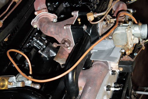
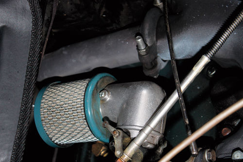
On some old collectible vehicles, the fuel line routing may be “Zeed” through the frame rail. This promotes fuel foaming leading to vapor lock. See Photo 12.
Fuel Line Repair: The fix to sharp 90° bends is to install a steel fuel line insert up over the frame with smooth bends.
Kinked fuel lines promote vapor lock.
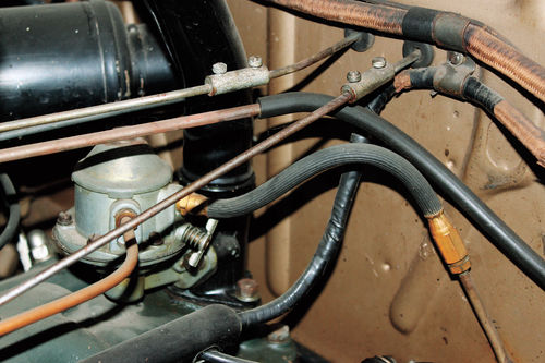
Copper lines “work harden,” become brittle and crack, which can be very unsafe. Replace copper fuel lines with steel fuel lines (Photo 13).
Replace the “flex line” at the pump inlet. Old flex lines harden, crack, collapse inside and suck air. The pump will not pump fuel with cracked or collapsed fuel lines causing lean mixture surging. This leads to block overheating and fouling of the spark plugs. See Photo 14.
And it’s not the new gas with ethanol that causes the failure! The old flex line is probably 20 years old and had old gas sitting inside.
The new fuel line rubber is designed to handle the new gasoline. This is all designed and tested via the SAE organization. (See “Gasoline Characteristics,” near the beginning of this write-up.)
Note: Fuel gauge cork floats may crumble with ethanol gasoline. Also remember that if the vehicle has been sitting for years, the old gas may have already been rotten, causing cork float failure.
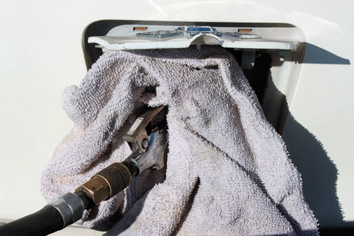
Clear the Fuel Line: Using air and a rag at the fuel tank filler pipe, blow fuel forward through the fuel line (Photo 15A).
Fuel Pressure: Measure the fuel pressure at the pump outlet or at the carburetor inlet. Plumb in a vacuum gauge that reads up to 10 psi pressure. Most carburetor fuel systems will measure from 3-7 psi during crank.
Disable the ignition system by grounding the coil wire at the distributor cap end. Crank the engine for five seconds. Record the pressure. Look up the specifications and compare the results. If the measured pressure is 1 psi lower or over the specified pressure range, install a new pump and a new flex line. Re-test the pressure and flow on new pumps.
In addition, measure the pump inlet vacuum. Hook up a vacuum gauge at the pump inlet and crank the engine. I have measured up to 10 inches of vacuum during crank.
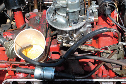
Fuel Flow: Next, measure the fuel flow. Install a plastic line and drape it into a plastic container. (Do not use a foam cup. It will melt!)
Ground the coil wire (distributor end). Crank the engine for 15 seconds watching for strong squirts. You should have around 1 ⁄2-1 cup of gasoline. If there is less, change the pump. See Photo 15B.
Also, look for clean fuel. If small rusty specs are visible, install a universal inline fuel filter near the carburetor.
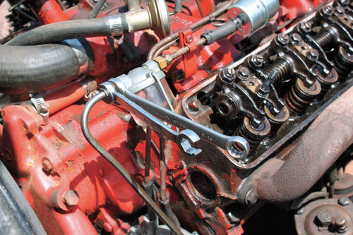
Seal fuel line connections using two “line” wrenches (Photo 15C.) Don’t use Teflon tape.
New Pumps: Measure the pressure and flow on the new pump.
If the new pump is more than spec, install a regulator and regulate the pressure to specification. The carburetor float needle is designed to handle specified fuel pressure without carb flooding.
As noted earlier, keep a fire extinguisher nearby, just in case!
If your collectible has been sitting for years, change the pump. If it’s not leaking during your pressure measurements, you can bet it will start leaking later while you’re on a tour.
Again, it’s not the gas; it’s old parts that fail after sitting for years with old gummy evaporated gas residue.
Eventually, the fuel in the line may form a “gumball” during long storage.
Other Block Overheating Causes
Timing Chain Retard: In extreme cases, timing chain stretch allows the valve timing to retard more than specification. This may lead to block overheating.
Review Motor manuals and check your engine’s timing chain. Replace out-of specification gears and chains.
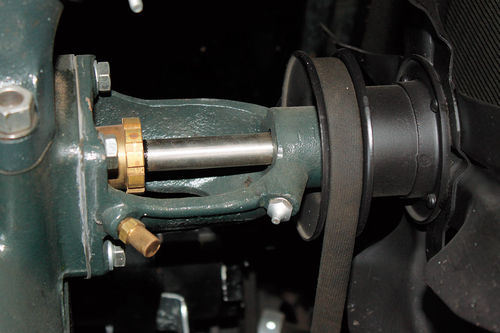
Water Pumps: Replace leaking water pumps. Look for shafts moving fore and aft (Photo 16).
Some water pump rebuild manufacturers are modifying the impeller. Contact these suppliers for their recommendations (pro & con). Coolant flow problems may be unique to various collectible year/make/model vehicles.
Head Gaskets: Head gaskets “blow out” between block water ports and cylinder bores. Combustion pressure forces coolant level to increase up into the radiator upper tank spitting coolant out the overflow tube.
The head gasket leak test is to fill the radiator to full up, then rev the engine to a steady 1500 rpm. Large bubbles from combustion leaks will usually surface causing coolant overflow.
Radiator repair shops also can check combustion gas content to analyze combustion coolant leaks.
Change the crankcase oil looking for water (or a milky mixture) in the oil. Drain the oil and install new oil.
The next step is to run a compression check to locate which cylinder is leaking.
In minor cases, the compression pressure may only be slightly less than normal specified compression pressures.
Remove the head and locate the head gasket leak. Clean the block of carbon around the head gasket outline.
Have the head crack checked and surfaced at an auto machine shop.
Clean the studs or head bolts and tap and die the nuts and/or head bolt threads. See Photo 17.
Apply Permatex copper spray gasket hi-temp sealant to the new head gasket. Let it set up to tacky and reinstall the head.
Oil the threads. Install bolts or nuts. Torque bolts or nuts to spec in the specified pattern. Then re-torque nuts or bolts after warm-up.
Block Cracks: Cracks happen because of low coolant levels and overheating.
Change the oil looking for a milky mixture. Install new oil. Run a compression check.
Again, check for combustion leaks by filling the radiator to the top. Rev engine to a steady 1500 rpm and watch for bubbles to surface.
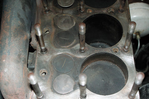
Remove the head and inspect for cracks. Most cracks in old “L-head” engines occur between the cylinder bore and the exhaust valve seat.
If cracked, seek professional advice on appropriate block and valve seat repairs.
The best crack repair kits, in my experience, are from Lock-N-Stitch, Inc. located in Turlock, California (locknstitch.com). Their repair pulls a crack together rather than spreading the crack apart.
Block Cleaning: Seek advice and help from your radiator repair shop on block cleaning. You have all heard of excess sand in block castings and rust buildup over the years.
If you can remove the core plugs, dig out the junk and back flush the block.
Some old engines have coolant passage covers on the block sides. Remove them, clean out the block and reinstall the covers.
During engine restoration (overhaul), have the block sandblasted and hot tanked prior to crack checking and machining.
Coolant Filters: Consider installing an in-line upper radiator hose filter and clean it often. This will trap loose rusty debris.
Repairs, Replacements and Modifications
By this point you may be thinking, “Gosh, I thought you would never get around to radiator replacement and modifications for controlling vapor lock and boilin’ over.” But all of the above must be corrected first, prior to getting into major repairs, replacements and/or sound modifications.
After all, how many times have you heard someone’s story that their engine wouldn’t crank or click, so the starter was replaced at great expense. With a new starter installed, “it still wouldn’t crank. That must’ve been a bad starter.” Install starter #2; no crank. Suddenly, somehow, the battery connections (hot and ground side) get serviced. The result is that the system cranks great at correct voltages. I see it all the time. The starter generally is not the cause for cranking problems.
That approach, starting with items like the battery connections, is the same that should be used for analyzing vapor lock and boilin’ over heating problems.
Do the “basics” first. All of the components we’ve discussed to this point must have been corrected, replaced, serviced and adjusted to specifications prior to making any major engine or cooling system repairs.
Radiators: Old radiators lose their bond between the fins and tubes. Cleaning and “rodding” out the core, quite often, may not be cost effective. Replace the core. Seek advice from your radiator repair shop. If you’re into show appearances, try to stay authentic. If you’re touring, purchase the modern “flat tube” radiator cores.
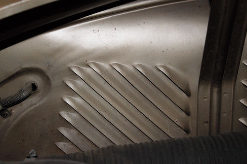
Under Hood Cooling: Inspect under hood obstructions that can restrict air flow.
Fender well and splash pan louvers, like those in ’40 Lincolns and ’35 Chryslers, provide greater air flow under the hood. See Photo 18.
Electric Fans: In some cases electric fans in the front of the radiator and/or the air conditioning condenser may help to improve radiator heat transfer and under hood air flow. This, quite often, is a modification on an old cooling system. Again, be sure to correct, test, repair, and/or adjust all tune-up items and cooling system anomalies discussed above prior to installing an electric fan.
For example, one collectible car owner recently shared this overheating story: His automatic transmission oil cooler sprung a tiny leak and the oil sprayed over the air conditioning condenser. Road dirt collected on the front condenser fin surfaces leading to air flow restriction.
Installing A Fuel Vapor Return Line: Many of the ’60s and ’70s cars were factory equipped with a fuel return line in the fuel pump or between the fuel pump and the carburetor to help minimize vapor lock. The return line was plumbed back to the fuel tank.
This leads us to an approach you may want to try on your older car equipped with a mechanical or electrical fuel pump.
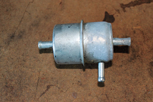
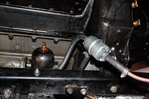
Purchase a Chrysler ’75-80 vintage fuel filter equipped with an inlet, outlet and a small return line nipple. The return line nipple has a small orifice (about 1/16”). Install this fuel filter just before the carburetor. See Photos 19A and 19B.
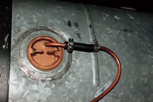
Install a 1/4-inch tubing line and route it adjacent to the fuel supply line back to the tank. Then route this fuel return line to the fuel cap. Modify the cap by soldering in a 1/4-inch piece of tubing. Connect the return line to the cap with a 1/4-inch rubber fuel line. Maintain the fuel tank vent. See Photo 19C.
The return line concept allows a small amount of fuel and vapor to return to the fuel tank. The supply of fuel to the carburetor will stay relatively cooler and will minimize fuel boiling or foaming.
Insulate the fuel line to reduce fuel temperatures. Remember, modern fuels start “boiling” at 90-100° F.
Fuel Line Attached To Firewall: Move the fuel line out 2-3 inches from the firewall and insulate. This works on older Ford V-8s. (Thanks for this tip from George Mitchell in Florida who rebuilds Ford V-8 coils.)
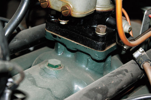
Carburetor Insulation: In some cases the carburetor may be exposed to excess block heat. Some older systems have a 1/4” phenolic or asbestos plate to reduce carb heat. Try a thicker plate to reduce heat (Photo 20).
Electric Pumps: An electric pump (vane type) may help in reducing vapor lock. Install the pump near the gas tank. Regulate this pump to the specified mechanical pump specification. Caution: do not install a high-pressure fuel injection pump on carburetor systems.
Factory Exhaust Systems: Model A Ford exhaust manifolds cause high underhood temperatures. See Photo 21.
In addition, you may want to try installing a shield between the fuel pump and exhaust pipe.
Exhaust Headers: As you may know, exhaust headers heat up underhood temperatures and, quite often, burn spark plug wires. Refer back to Photo 10 in last month’s installment.
And while you’re working, please remember that our old cooling systems can be as much as 100 years old, and there may be several causes for our collectibles to experience vapor lock and boil over.
All of the above is based on my nearly seven decades of wrenching and testing experience. Furthermore, from 1946 to 1951 I was fortunate to receive valuable experience from my father, Earl Webb. He operated an auto repair business in North Las Vegas, Nevada (summertime, 100-120° F). For more, visit Milttheinstructor.com


