
Understanding and maintaining a breaker-point ignition system.
IGNITION SYSTEMS ARE designed to ignite the combustible air/fuel mixture in the engine’s cylinders. Exactly how this is accomplished may seem a little bit mysterious, but closer examination reveals the process is really rather simple.
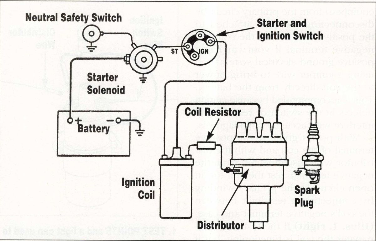
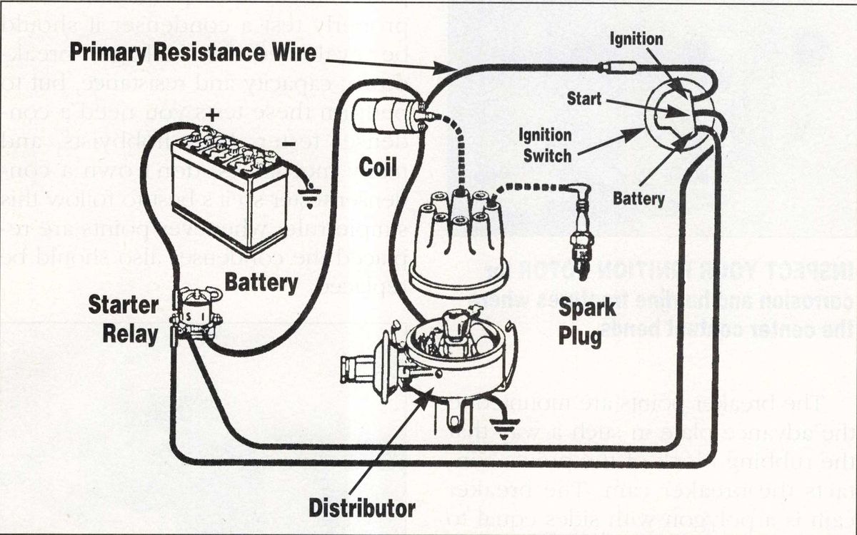
The ignition system utilizes two distinct circuits, usually called primary and secondary circuits, or low-tension and high-tension circuits, respectively. The primary circuit carries low voltage, ranging between about nine and 14 volts (or six to eight volts if the car has a six-volt electrical system), and the secondary circuit carries high voltage, as high as 20,000 volts or more.
The primary circuit, which derives its current from the car’s battery and generator system, feeds low voltage into the ignition coil. The secondary circuit, which is fed high voltage by the operation of the coil, delivers the high voltage to the spark plugs.
Voltage can be thought of as the electrical power that forces current through the circuit in opposition to the resistance present in the circuit. Higher resistance in the circuit will require higher voltage if the current is to get all the way through the circuit. In order to create a spark from a spark plug, the current must pass through the air gap between the spark plugs’ points. Since this air gap has tremendous resistance to the flow of current, the voltage necessary to overcome the resistance must be very high. That is why it is necessary for the secondary ignition circuit to produce thousands of volts.
How the Coil Functions
The low-voltage current in the primary ignition circuit is changed into the high-voltage current in the secondary ignition circuit by a process called induction. An ignition coil is really a specialized type of induction coil.
By means of an electromagnetic field, the low-voltage current induces the formation of the necessary high voltage current.
The ignition coil contains two coils of wire, one for the primary circuit and the other for the secondary circuit. Accordingly, the two coils of wire are called primary windings and secondary windings, respectively.
With the breaker points closed, the primary circuit is completed and current flows through it. Whenever current flows it is surrounded by a magnetic field. This magnetic field created by current flowing through the primary circuit is highly concentrated as a result of the many turns of the respective wires that form the primary and secondary windings. The magnetic field is further concentrated by the presence of a solid iron core in the ignition coil.
When the breaker points open, the primary circuit is interrupted and the current stops flowing. Without current flow, the magnetic field collapses. When the magnetic field collapses, most of the energy stored in it is transformed back into electrical energy, producing a very high voltage in the ignition coil’s secondary winding.
The amount of voltage induced in the secondary windings of the ignition coil is determined by several variables:
the voltage in the primary circuit;
the size of the wire and number of turns in both the primary and secondary windings;
the size of the iron core in the coil; - and the ignition condenser, which helps build up voltage in the secondary winding.
The amount of voltage actually required to produce a spark at the spark plug is also determined by several variables, including the size of the gap between the plug’s points and the compression pressure of the cylinder. A larger plug gap and a higher compression pressure both necessitate greater voltage if the current is to jump the gap between the spark plug’s points.
Evaluating the Ignition Coil
A defective ignition coil can prevent the engine from running, lead to difficulty starting the engine or cause engine misfiring. There are several relatively simple tests you can perform to determine if you coil is defective. The first step in testing the coil, is to eliminate the ignition switch and the ignition resistor (if your car is so equipped) from the primary circuit by disconnecting the wire attached to the positive terminal on the coil (the negative terminal if your car has a positive-ground electrical system) and using a jumper wire to bring power to the coil directly from the battery. This is recommended because certain defects in the switch or resistor will interfere with accurate coil diagnosis.
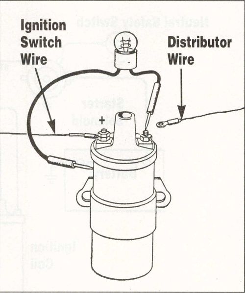
With power going to the positive terminal of the coil and with the distributor wire disconnected from the negative terminal, test the coil for an open circuit in the primary winding by connecting a test light between the coil’s negative terminal and case. (Illustration. 1) If the test bulb illuminates the coil is functioning, but if the bulb fails to illuminate, the coil has an open circuit in the primary winding.
Disconnect the power wire to the positive terminal and the distributor wire to the negative terminal, then test the coil for grounded circuits in the windings with a 110-volt bulb. (Illustration. 2) The bulb should not light and no sparks should be seen where the contact is rubbed on the coil’s case. If the bulb lights or tiny sparks are observed when the contact is rubbed on the case, the coil is defective.

If you have access to an ohm meter and an amp meter, it is advisable to test the resistance and draw of the coil. Compare the readings obtained with the specifications for your particular car. Most good shop manuals contain these specifications in the tune-up or ignition sections.
Causes of Coil Failure
If you discover the coil is defective and must be replaced, it is advisable to determine if there is a malfunction elsewhere that caused the coil failure. Sometimes simply replacing the coil does not solve the problem. If you do not remedy any underlying maladies, you may ruin another coil.
A common cause of coil failure is accumulated moisture inside the coil’s case. Moisture causes corrosion that leads to increased resistance to the flow of current. Most original equipment coils are sealed against moisture at the point of manufacture by crimping the edges of the top over the edge of the case. Begin the evaluation of your coil by inspecting the junction between the top and the case for any defects that could permit moisture to enter. Also examine the case for any breaches that would allow moisture to enter. I have seen coils fail because of tiny pin holes caused by corrosion, so be particularly attentive to any rusty areas.
Another common cause of coil failure is excessive heat. It is essential for the internal components of the coil to be insulated from one another and this is accomplished by means of insulating cylinders that separate the secondary winding from the iron core, the primary winding from the secondary winding, and the primary winding from the case. In addition, the wires of the windings are each encased in insulation. Excessive heat will break down the insulation, causing internal shorts and eventually leading to complete coil failure.
Heat is a natural byproduct of current flowing through a conductor, so it is inevitable that a coil will get hot when it is operating. As a result, coils are designed to withstand a typical level of heat without sustaining damage. When the voltage feeding into the coil increases due to a problem, the increased voltage leads to increased heat. Even a small increase in voltage will translate to a large increase in heat. For example, if the current increases from eight volts to 12 volts (an increase of 50 percent) the heat generated will double (an increase of 100 percent).
In order to reduce the voltage entering the coil, and thus reduce the heat build-up, a resistor is incorporated into the primary ignition circuit. The diagrams below illustrate several types of resistors commonly used by the automobile manufacturers. In a 12-volt system the resistor reduces the voltage to the primary windings in the coil to about six to eight volts when the engine is running. There is, however, a provision that allows the full 12 volts to reach the coil when the engine is being started. This provides a hotter spark when it is needed for initial start up, but after the engine starts the voltage to the coil drops to protect the coil from excessive heat.
Use a volt meter to measure the voltage entering the coil when the ignition key is in the on (not the start) position. If you measure more than eight volts in the primary circuit where it connects to the coil, the resistor is missing or not functioning. The malady must be remedied or coil failure will result.
In addition to excessive voltage, another cause of heat build-up in the coil is an uninterrupted current flow in the primary circuit. Remember that when the breaker-points open, the primary circuit is momentarily interrupted. As the engine runs, this constant interruption in the flow of current through the primary circuit helps to keep it within an acceptable temperature range. If the ignition key is accidentally left in the on position for an extended time and the points are in the closed position, the uninterrupted current through the primary circuit causes the primary winding to overheat (after 10 to 15 minutes the coil will become too hot to touch) and will ultimately lead to coil failure.
Another potential cause of coil failure is excessive resistance in the secondary circuit. A coil will continue to build voltage in the secondary circuit until the voltage is sufficient to overcome any resistance present, or until the coil reaches its peak output. There is a maximum amount of voltage a given coil is capable of developing, but its maximum output is normally considerably more than what is required to create a spark. This “over-capacity” is designed into the coil so that it is not continually functioning at maximum capacity. Excessive resistance in the secondary circuit will cause the coil to operate at or near its maximum capacity and this puts an abnormal strain on the secondary winding. Abnormally high voltage consistently flowing through the secondary circuit will break down the insulation between the layers of the secondary winding.
Increased resistance in the secondary circuit can be caused by a variety of factors. Excessively wide spark plug gaps (.005 above specs) increase the high-resistance air space between each plug’s electrodes and can therefore put a significant strain on the secondary circuit. Likewise, if there is too much space between the ignition rotor and its contact on the distributor cap, or corrosion at the point of contact, increased resistance in the secondary circuit will result.
In addition, incorrect or defective radio suppresser devices can cause abnormally high resistance in the secondary circuit. A segment of the spark discharge can interfere with the reception of radio waves and cause humming or static in the car’s radio. Resistors designed to eliminate or reduce only that segment of the spark discharge are sometimes incorporated into the ignition system. After a coil failure, it is worthwhile to locate and evaluate every component functioning as a radio suppresser.
Radio suppression resistors may be incorporated into the secondary cable that connects the coil to the distributor cap, the center tower of the cap itself, or in some cases, the distributor itself. A resistor may also be attached directly to the coil, incorporated into each spark plug wire (carbon-impregnated-core ignition wires have been commonly used to suppress radio interference for many years) or built into the spark plugs (“resistor” plugs).
The best way to evaluate the resistors is to test each with an ohm meter and then compare the resistance measured with the specification for each one. Often the specifications are written on the resistor, but sometimes you will have to do research to discover the specifications. You may be unable to find specifications, or you may not have the ability to test the components yourself even if you do find the specs.
If this is your situation, I recommend these five common sense approaches:
Compare the radio suppression devices on your car with those shown in your shop manual and eliminate any that were not original equipment.
Have a shop that specializes in automotive electrical components test your O.E.M. resistors for you if you can’t test them yourself.
If you can’t test them yourself and you can't find anyone to test them for you, and you suspect that your coil failure(s) are related to a defect in one or more of the resistors, simply replace them if they are available. They are typically inexpensive.
If the resistors aren’t available or you don’t want to spend the money to replace them, remove them. However, the radio interference that results may drive you crazy.
Keep in mind that while each individual component may be functioning properly, the cumulative effect may provide too much resistance. Be particularly attentive to the addition of non-original equipment resistors such as resistor spark plugs, resistor spark plug wires and a distributor cap with a built-in resistor.
Distributor Basics
A distributor distributes the electrical energy in the coil’s secondary circuit to each of the engine’s spark plugs in the proper sequence and at the proper time intervals. It is typically driven by an integral gear on the camshaft that mates with a gear attached to the bottom of the distributor drive shaft. The principal components of a typical distributor include the cap, rotor, housing, main shaft, breakerpoint assembly, breaker cam, advance weights and, if so equipped, vacuum-advance mechanism.
Distributor Cap and Rotor
The distributor cap and rotor are molded from a resinous plastic compound that serves as an insulator. The cap has many highly conductive brass terminals molded into it. The center brass terminal receives the high voltage cable from the coil. At equally spaced intervals around the perimeter of the cap are terminals that receive the spark plug wires from each of the engine’s cylinders. The rotor also has conductive metal molded into it. This metal extends from the middle to slightly over the edge and completes the circuit from the cap’s center terminal to each of its outer terminals in sequence. The rotor mounts onto the top of the distributor main shaft by either simply sliding onto the shaft or by small screws that hold it in place. Distributor caps are normally reliable, but do occasionally develop problems. Begin your diagnosis of the cap’s condition by examining it carefully. Look for corrosion inside the cap where the center terminal or outer terminals receive high voltage from the rotor. Minor corrosion can be cleaned up with fine sandpaper or a fine file, but if the terminals are pitted or worn away (as eventually happens) the cap should be replaced. Also watch for cracks in the cap.
Hairline cracks will seriously impair the cap’s function. Because electricity always follows the path of least resistance, and a crack offers less resistance than the spark plug wire and spark plug, high voltage will be diverted through the crack and will either “jump” onto the wrong terminal, flow through one of the metal straps holding the cap, or simply discharge into the air. An excellent diagnostic technique is to observe the cap in the dark with the engine running. Any cracks will become immediately apparent because you will actually see the electricity passing through the crack and arcing to the nearest ground or into the air. A cracked cap should be replaced.
The ignition rotor can occasionally develop problems. Examine the met al contact molded into the rotor. Minor corrosion or surface defects can be corrected with fine sandpaper or a small file. Serious pitting or disfigurement dictates a rotor replacement.
Also look for tiny fractures in the strip of metal. The end that contacts the outer terminals of the cap is normally molded into the plastic but the end that contacts the center terminal rises above the rotor and is kind of “springy”. I have seen the metal strip crack at the point where it bends and rises up to meet the cap’s center terminal.
One more thing to look at is the rotor’s retention mechanism. Some distributors have a slot in the top of its shaft that mates with a tang on the rotor. Other distributors have a plate on the top of the shaft that has some sort of key way, such as a square hole on one side and a round hole on the other, so the rotor can only sit in its correct position. If the tang or keyway is worn or distorted, the rotor may move around and make it impossible to accurately time the ignition system. Examine the retention mechanisms and try to wiggle the rotor while it is mounted to make sure it will stay in its correct position.
If you are replacing a rotor, note its position before you remove it and make certain the metal contact of the new rotor is in the same position as the contact of the old rotor.
The Distributor Housing And Main Shaft
Original equipment distributor housings are typically made from rather heavy castings and are therefore quite durable. But even though they rarely break, give your distributor’s housing a once over for any cracks if it is out of the engine.
The only normal service items that are part of the housing are the two bronze bushings that are pressed into the top and bottom of the housing’s bore. The distributor’s main shaft spins in these bushings and over time they will wear out. With your distributor out of the engine, try to wobble the drive shaft back and forth in the housing bore. If you detect more than a slight amount of play, it is a good idea to replace the bushings. The old bushings can be extracted with a tool designed for the job. (Eastwood, Snap-On, Mac and many other tool suppliers sell bushing removers.) Or, if you are very careful, you can drill them out. Press new bushings into the housing and hone them slightly, if necessary, to get a free but snug drive shaft fit.

Unlike their housings, distributor main shafts do sometimes wear out or suffer damage. Since the bronze bushings the shaft rides in are much softer than the hardened steel shaft, the bushings should wear while the shaft should remain unscathed. Sometimes, however, the shaft will get visibly worn at the points where it contacts the bushings and will wobble around even when new bushings are installed. I have also occasionally seen shafts damaged on the bottom where they have a tang that fits into a groove in the end of the oil pump drive shaft. Sometimes the tang gets distorted or broken. This is particularly likely to happen if the oil pump jams.
In order to thoroughly inspect the main shaft, it must be removed from the housing. Remove the lower drive gear by knocking out the roll pin that retains it to the shaft and slipping it off. Make note of the shims Cf any) that are between the gear and housing and replace the shims when you reinstall the gear. If the main shaft has grooves worn in it or other visible damage, replace it with a new or good used one. When replacing a shaft, it’s a good idea to also replace the bushings the shaft rides in. If the shaft is damaged where it contacts the bushings, it is likely the bushings will also be damaged.
Breaker Point Assembly And Breaker Cam
The breaker point assembly consists of several components whose main function is to locate the breaker points and related parts and provide the mechanism by which the ignition timing is automatically advanced. A breaker plate is firmly anchored to the distributor housing with screws and the advance plate is then attached to the breaker plate in a way that allows it (the advance plate) to move. Automatic advance of the ignition timing is realized through the action of the advance weights and springs and when so equipped, by means of a vacuum actuator.

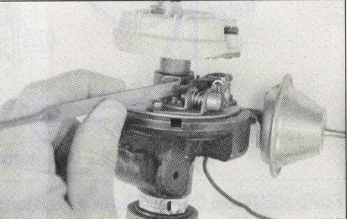
The breaker points are mounted to the advance plate in such a way that the rubbing block of the points contacts the breaker cam. The breaker cam is a polygon with sides equal to the number of engine cylinders. The breaker cam is mounted to the distributor drive shaft and as the drive shaft rotates, the cam opens and closes the points.
There are several problems that can develop in the breaker cam and breaker point assembly components. Malfunctioning or ill-functioning points are the most common problem. While there are other possible causes of premature point failure, the most prevalent are excess voltage flowing through the ignition’s primary circuit and grease or oil on the points’ contact surfaces.
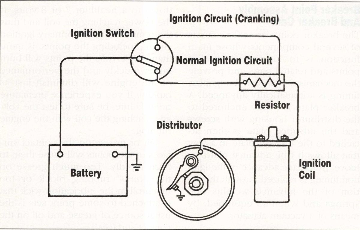
The point set, like the ignition coil, was designed to operate at less than 12 volts. A ballast resistor, resistance wire, or some other resistance device should be located between the ignition switch and the coil in order to bring the 12 or more volts coming out of the ignition switch
down to a healthier 7 or 8 volts. If the power reaching the coil and thus the remainder of the primary ignition circuit, including the points, is more than 7 or 8 volts the points will burn rather quickly and the performance of the engine will diminish just as rapidly. If you experience premature point failure, be sure to test the voltage reaching the coil with the engine running.
Oil or grease on the contact surfaces of the points will cause them to burn rapidly. Too much grease on the points’ rubbing block or too much oil in the lubrication wick that is attached to some point sets is the usual source of grease and oil on the contact surfaces.
A defective condenser is another potential cause of point failure. To properly test a condenser it should be evaluated for leakage, breakdown, capacity and resistance, but to perform these tests you need a condenser tester. Most hobbyists, and many mechanics, don’t own a condenser tester so it’s best to follow this simple rule: whenever points are replaced the condenser also should be replaced.
If your Delco-Remy ignition points are mildly pitted, you can usually clean them with a small, fine file. Auto-Lite, on the other hand, recommends against filing points because it claims that the material its points are made of is so hard that microscopic pieces of the file will actually break off and get embedded in the contact surfaces where they will produce high spots that will concentrate current and heat in extremely small areas. A fail-safe alternative to filing points, of course, is to replace them.

In addition to malfunctioning points, there are other possible problems with the breaker point assembly and breaker cam. The grease beneath the advance weights can become gummy and prevent the weights from moving and the advance weight springs can fatigue and offer too little resistance to the centrifugal action of the weights. You can clean and lightly lubricate the area beneath the weights and replace the springs with new ones if they look lame, but the best way to test and set up the advance mechanism is on a distributor machine. This type of machine enables you to evaluate the performance of the points as well as the advance mechanism and allows you to custom tailor the advance curve of the distributor to match the other characteristics of your engine. A distributor machine will also permit you to observe the function of the breaker cam. It is possible for the cam to wear enough to hinder engine performance and if this occurs the cam should be replaced. Most engine builders and machine shops have distributor machines and will test your distributor for a small charge.
Vacuum Advance Mechanism
The purpose of a vacuum advance mechanism is to advance ignition timing under certain conditions. The vacuum advance contains a spring loaded diaphragm that rotates the breaker plate assembly in the distributor when it receives vacuum and thus advances ignition timing. The vacuum advance is connected to a port on the atmosphere side of the throttle plate in the carburetor. As a result, no vacuum is directed at the advance during idle or under hard acceleration and spring tension retards the breaker plate. When cruising or accelerating moderately, vacuum is directed at the unit and the breaker plate is rotated to advance the timing.
Trouble arises with vacuum advance mechanisms when the vacuum supply to the unit is inadequate, the diaphragm is ruptured or the linkage connecting the diaphragm to the breaker plate is binding. Use a vacuum gauge to test the supply of vacuum to the advance unit. At idle and upon hard acceleration there should be little or no vacuum and at steady cruising rpms there should be at least 12 to 14 inches (Hg, mercury) vacuum.
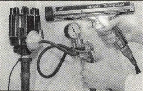
Test the advance unit for a ruptured diaphragm by applying about 18 inches (Hg) vacuum to it with a hand-held vacuum pump and observe the gauge on the pump. The unit should hold vacuum for at least a couple of minutes if it is in proper working order. If the diaphragm is leaking, replace the advance unit.
Even if your advance unit is not leaking, it still may not be working properly. Vacuum advance units are calibrated differently at the factory according to the specifications of the diaphragm spring installed. Stiffer springs will cause the advance action to begin later and can limit the total advance achieved and lighter springs will do the opposite. If you have a stock engine in your car, check the vacuum advance specifications in your shop manual and compare them to the unit on your car. To test your unit, connect a vacuum pump to it and start the engine. Apply the vacuum force specified in your shop manual and observe the engine’s timing mark with a timing light to see if the ignition advances the proper amount when the vacuum is applied to the vacuum advance. If your test indicates that the advance unit deviates from proper specification by more than a couple of degrees, replace it with a new one.


