TAKING A CLOSER LOOK AT COTTER PINS
They’re Among the Cheapest Components on Your Car or Truck, But Don’t Underestimate Their Importance to Your Vehicle’s Safety and Dependability.
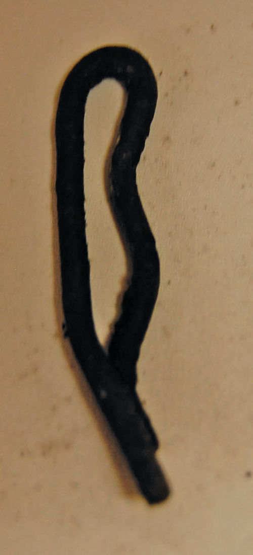
Americans call them “cotter pins” and British car enthusiasts call them “split pins.” They resemble the bobby pins that were in your mom’s sewing box, except that they do not have a “bumpy” prong like a bobby pin. In addition, while a bobby pin is typically used to clip fabric or hair together, a cotter pin is generally used to lock hardware or parts in a fixed position. That’s why some restorers call them “cotter keys.”
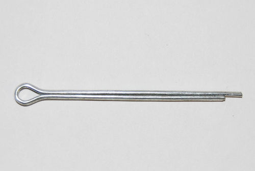
Cotter pins are made from wire bent over bobby pin style to form two prongs. At the top is a loop that resembles the “eye” of a sewing needle. This is actually called the “head” and prevents the cotter pin from passing completely through the locking hole drilled in other hardware or parts. The slightly curved area below the head is the “neck.” To use a cotter pin, you squeeze the two prongs together so both can pass through the locking hole. When the prongs emerge on the other side of the hole you bend them back.
A Variety of Inexpensive Choices
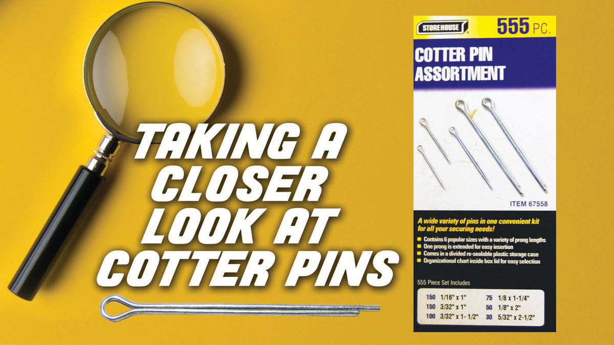
Cotter pins are simple and cheap. At your local Harbor Freight store you can buy a kit with 555 cotter pins in six popular sizes for about $8. According to Wikipedia, American cotter pins come in 18 different sizes, each with a specific hole size. Some of these are suited for particular size bolts. There are also eight metric sizes, each with a specific hole size and bolt size application.
Most cotter pins are made of soft metal such as mild steel, brass, bronze or aluminum. This makes them easier to install and remove, but it can reduce resistance to shearing. So other materials such as stainless steel are used to make stronger cotter pins when it is necessary to have a fastener that can resist strong metal shearing forces.
The cotter pins in the Harbor Freight kit are known as extended prong cotter pins. They have one side longer than the other so it’s easier to separate the prongs. In some cases, the extended prong is curved or beveled and overlaps the shorter prong, making the cotter pin easier to install.

The most common cotter pin is the extended prong square-cut type. Standard cotter pins have equal length prongs. Other styles of cotter pins are the mitered end type, the bevel end type and the hammer lock type. Hammer lock cotter pins are installed by hitting the head with a hammer to secure the pin. This design pushes the shorter prong forward, spreading the pin to hold it in place.
Taking a Closer Look…


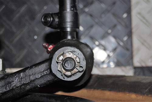
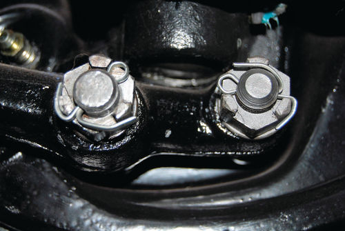
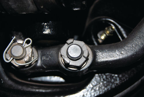
Cotter pins are found more frequently on older cars than they are on modern vehicles, but you will still see them used today on wheel spindles, suspension parts, ball joints and steering links, usually to keep castle nuts (nuts with a “castle turret” side) locked in place. They are also used to hold clevis pins in place on various linkages, such as a carburetor or gearshift linkage.
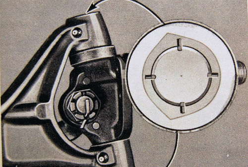
Let’s look first at the castle nut application.
The bolt that a castle nut threads onto has a hole drilled though it at a specific point. That’s the point where you want to lock the nut in position. Thread the castle nut in until the drilled hole shows up in two opposite “windows” or “turrets” in the castle nut. Automotive Technology instructor Dave Sarna points out that very early castle nuts had only three widely-spaced turrets. With these, you had to get the nut positioned so that the cotter pin would pass through two turrets that are not directly opposite each other. Once the hole shows up in the turrets on both sides of the bolt, you can push your proper-sized cotter pin through the hole. On one side the head of the cotter pin will lock into one of the turrets in the castle nut. On the other side, the cotter pin’s prongs are bent back over the end of the bolt in opposite directions, thereby locking the castle nut tightly in position.
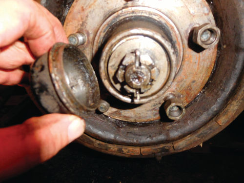
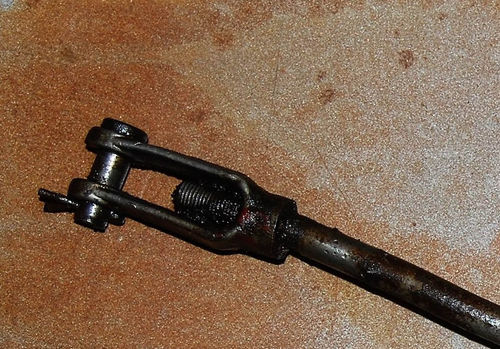
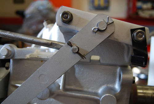
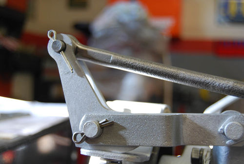
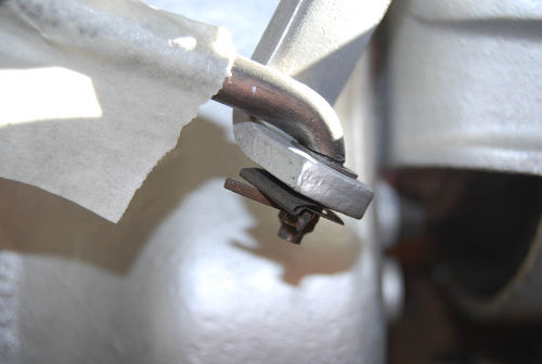
As we said, cotter pins are also used to lock clevis pins—like those used in carburetor and transmission linkages— in place. The linkage rod will have a U-shaped end that fits over a second piece of the linkage with one leg of the “U” on each side of the connected piece. The U-shaped end and the second linkage part have holes drilled through them. The clevis pin—which has a hole in the end—slides through the holes in the other parts until the ridge at its head stops it from going completely through the hole. The end of the clevis pin with the hole protrudes on the opposite side. A washer is placed over the protruding end and a cotter pin goes through the clevis pin hole to lock it in place.
As you can see in the accompanying photos, even though the clevis pin is locked in position on a horizontal plane with a cotter pin, the linkage rods can still rotate freely over (or with) the clevis pin as the linkage parts move back and forth. The clevis pin serves as kind of an axle for the linkage parts and the cotter pin holds the parts together.
Don’t Skimp on These
Although regular cotter pins are cheap, they play an important role in holding car parts together. Installing a cotter pin properly protects life and limb. In a worst-case scenario, a missing cotter pin could lead to a wheel falling off or steering or suspension components coming apart while you’re driving your vehicle at highway speeds.
Always use brand-new cotter pins. Like we said, they’re cheap. To avoid any possibility of metal fatigue problems, do not reuse old cotter pins. After being bent once, the prong of an old cotter pin (especially a rusty one) could break off if you bend it again.
Pay Close Attention to Size
Cotter pins come in different diameters and you need a size that will slide through the hole with a tight, nonsloppy fit. The size of the head and the prong lengths are important, too. The usable length of a cotter pin is measured from under the head to the end of the shortest prong. You can use a cotter pin that is too long and shorten the prongs with side cutters, but you can’t stretch a cotter pin that’s too short. The cotter pin used should be the largest that fits through the hole and the head must be bigger than the hole.
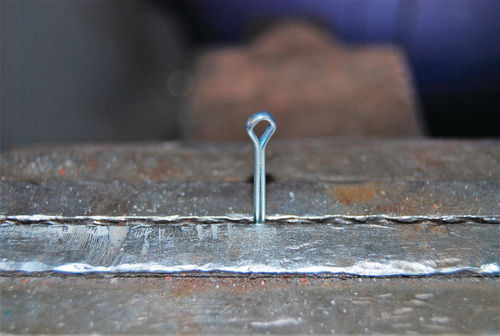
The recommended way to install a cotter pin is to place it so the head lies vertical to the work surface. Insert the cotter pin into the hole of the bolt. Pull the pin down until it reaches the point of contact. After pulling it to the maximum, spread the prongs in opposite directions. One prong should be bent up over the bolt. Bend the other end downward over the bolt. Use side cutters to trim the prongs so they don’t stick out and scratch you. This also makes it easier to remove a cotter pin. Use a hammer to tap the prongs over the bolt so the ends are out of the way. Dave Sarna points out that with a vertical hole position, you should slide the cotter pin in from the top. Then, even if both of the prongs were to break off, the pin would still somewhat stay in the hole, instead of just falling out.
Before World War II, Rolls-Royce factory mechanics put their cotter pins in a vise so that about half was showing. They would then grab the head with a pliers and twist it 90 degrees. Once this technique is mastered, the cotter pin will be easier to install and the whole assembly will look neater. And speaking of a neat look, most cotter pins will look better installed if the excess sections of the prongs are hammered into place, rather than being “cinched up” with needle nose pliers. Aircraft builders will often hammer the prongs back around the notches in a castle nut. When done properly, this looks cool.
Another install method is to position the cotter pin so the head is horizontal to your work surface. Insert the cotter pin into the hole of the bolt. Use pliers to pull the prongs through and bend them in opposite directions. Leave a small part of the prongs showing and snip off the rest with your side cutters. Bend the prongs back with pliers and stick them back into the bolt hole. This secures the castle nut with no loose ends sticking out. The prongs must be long enough to keep the cotter pin from slipping through the bolt.
Taking Extra Precautions With Aircraft
Dave Sarna has gone over 200 mph at Bonneville and recently purchased his first airplane, a classic 1964 model, which he’s been working on. After fact checking this story, he pointed out that many racing organizations and aircraft regulations require the use of safety wire over cotter pins to lock parts in position that much more securely. The Experimental Aircraft Assoc. (EAA) has videos about the installation of cotter pins and safety wire in aircraft applications posted on the Internet in case you are interested.
Removal May Be Easy Or…
It is usually a fairly simple job to remove old cotter pins by hand once the prongs are straightened out. Duckbill or needle nose pliers sometimes come in handy for giving a cotter pin a good yank. At other times, you’ll find yourself positioning a screwdriver blade against the “hole in the head” and then hammering the bottom of the screwdriver. The goal here is to use the screwdriver blade as a tool to drive the cotter pin up and out. It is usually a fairly simple job to remove old cotter pins by hand once the prongs are straightened out. Duckbill or needle nose pliers sometimes come in handy for giving a cotter pin a good yank. At other times, you’ll find yourself positioning a screwdriver blade against the “hole in the head” and then hammering the bottom of the screwdriver. The goal here is to use the screwdriver blade as a tool to drive the cotter pin up and out.


There are times when none of these techniques work. As Sarna puts it, “All mechanics have had cotter pins that won’t come out by the top loop. The legs get broken off in a removal attempt and you have just what’s left in the hole. It’s possible to use a socket and a 1 ⁄2-inch breaker bar to force a nut over the remains of a cotter pin, but the little buggers will do their job right to the bitter end and not let the nut vibrate loose.”
Personally, we’ve had to cut, chop,
grind and heat cotter pins to remove them. If you consider the reason cotter pins get difficult to remove, you’ll realize that you are trying to pull the cotter pin out in a straight line. If there are any twists in the cotter pin. They will cause it to stick. You need a rightangle pulling motion instead of an in-line pulling motion.
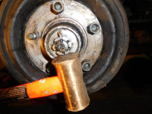
One way to create this is to use an old “scissors style” drum brake tool. Position the tool so that you can grab the cotter pin’s “eye” with one end of the tool or the other. You’ll find the scissor design provides you with extra leverage that will pull out the pin.
Advances In Cotter pin Technology
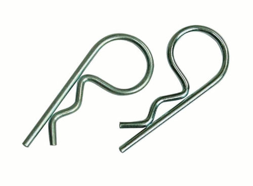
The standard old-fashioned cotter pin that we’ve spent time talking about here is not the only kind available today. A more modern type looks somewhat similar to a capital letter “R” except that the angled “leg” is springloaded. These get inserted by pushing the straight leg far enough down through the locking hole so that the wavy spring-loaded leg will be pushed against the part you want to lock in place and hold it there.
These R-clips (also known as R-pins, R-keys, hairpin cotter pins, hairpin cotters, bridge pins, hitch pins and spring cotter pins) are handy for securing the ends of round shafts like axles and clevis pins. They also come in handy for locking trailer parts in position. There is a double-loop type with a wider range of shaft sizes that spreads out stresses more evenly and lasts far longer. R-clips are made of a harder, rounder wire than cotter pin wire. They work like cotter pins, but are easier to remove and are re-usable.


