Restoring a Vintage Vehicle Heater

October 1, 2018 | By John Gunnell

Older Vehicles Don’t Always Have Them, But If There’s One Under Your Dash, You’ll Want It In Peak Condition for the Coming Colder Weather.

An interesting thing about working on older vehicles is that they “talk” to you about bygone days when life wasn’t as complicated as it seems now. Before World War II and in the early postwar years, most vehicles were pretty simple machines. The bulk of cars and trucks in those times did not have a lot of options and accessories. Many were sold without the things we take for granted today… such as a hot water heater built into the dashboard.

In this view you can see some of the short sheet metal screws—the ones at the top corners right above the heater core opening. Be careful, they are easy to lose.

Bakelite elbows are hot air outlets. The edge of one crumbled when it was removed. The doors in front and on the sides can be opened or closed to somewhat regulate heat levels.

Here you’re looking at one end of the housing cover. The air outlet elbow fits in the circular opening. You can also see how the side doors open. Some 3-in-1 oil helps to improve their operation.

The heater core is attached to this sheet metal pan that fits inside the housing. Be gentle when handling—those aluminum fins bend easily.

A two-piece bracket (twisted vertical rib) holds the motor in position over the opening in the rear housing cover and over the heater core. In and out pipes go into the heater core.

This photo gives you a good idea of how the heater core is sandwiched in between the sheet metal pan (top) and the housing cover (bottom).

The fan motor and fan were media blasted down to bare metal. The old paint came off these parts very easily. Some openings were sealed with duct tape.

The old wiring had a braided fabric covering and there were numerous breaks in the 65-year-old fabric. The on-off knob still worked perfectly and looked pretty good, too.

Here’s the housing after it was blasted in a media blasting cabinet. The plastic knob on the door was removed and the one good elbow was taped up to keep the media from hitting it.

The front (upper) and rear (lower) halves of the heater housing after they were cleaned and media blasted. Note the fixed half of the motor bracket on the rear housing.

Rust-Oleum Aged Copper paint was used on the heater housing parts. The Universal Advanced Formula metallic paint and primer in one worked well.

Here’s the rear half of the heater housing (and motor bracket half) after being painted. The inlet and outlet pipes were also blasted and then polished until shiny.

The front half of the heater housing was also painted with the plastic knob removed and Bakelite elbow taped to keep paint off. Open the doors so they don’t get painted shut.

In this view you can see the motor after it was painted and the wiring that was reinforced with black shrink tubing.

Almost forgot to mention that we used an Eastwood radiator comb to straighten the aluminum heater core fins. The six combs fit different fin patterns.

Long slotted screws are used to hold the sheet metal pan to the housing with the heater core sandwiched between them. The heater core has not been painted yet.

Edges were taped and the heater core was painted with Eastwood’s Radiator Black, a very thin paint that won’t clog openings.

With everything cleaned, blasted and painted, it was time to start the reassembly process with our radiator core sandwich.

This illustrates how the motor is clamped in place. The long screw through the clamp actually changes the fan’s position as it is tightened until the blades don’t hit the edges.

A bird’s-eye view of the rear of the heater. Note the nuts on the long screws in the 3 o’clock and 9 o’clock positions. These hold the housing halves.

The unit is assembled and looking “purdy.” The edge of the right-hand Bakelite elbow took a beating so it will need to be sealed to the circular opening with epoxy.

Here’s the rear view with all the pieces painted and assembled. This job took a while, but it was worth the time involved.

Here’s the restored heater with two Bakelite elbows in place. The clamps on the inlet/outlet pipes at the rear hold the heater to the firewall and hoses attach to them.

Heaters Were Different Then

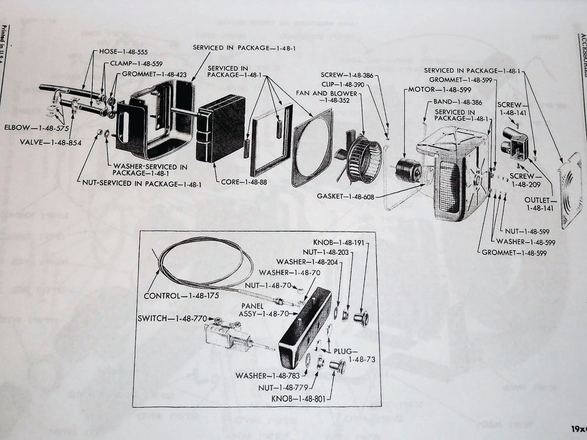
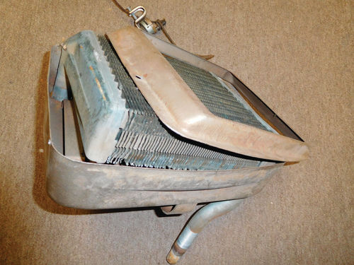
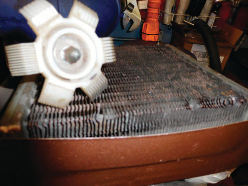
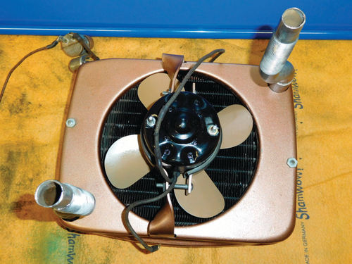
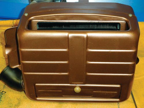
Even when a heater was installed in the earlier years, it was often an art deco-looking contraption that was hung under the dashboard on the passenger side of the car, preventing anyone “riding shotgun” from stretching their legs out too far. The typical heater consisted of a small radiator (heater core) mounted inside that art deco housing which was made of thin sheet metal. The housing had metal inlet and outlet pipes that routed engine coolant through the heater core.

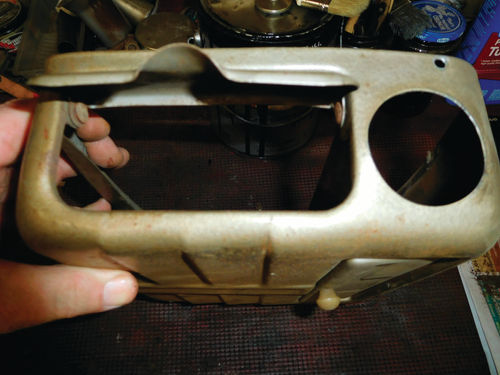
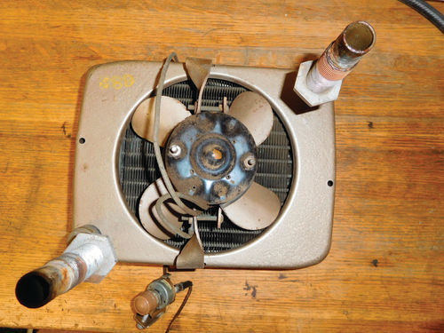
An outlet (or outlets) made either of metal or Bakelite sent heated air flowing into the vehicle’s passenger compartment. Also, inside the sheet metal heater housing were a small electric motor to turn the fan, sometimes a round, cage-like part called a blower and a small fan with (usually) four or more blades.

Other parts of the system included a switch, the electrical wiring and small doors in the heater housing that were used to control how much heat was blowing on the front passenger’s feet. As noted, the heat was generated by warm engine coolant flowing through the heater core. One problem that age brought was a leaky heater core that let coolant drop on the passenger’s feet. Electrical issues were the next biggest bugaboo.

The Unit Seen Here

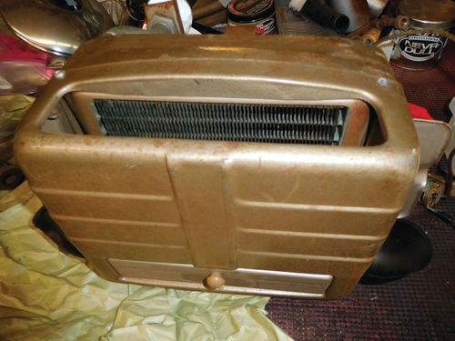
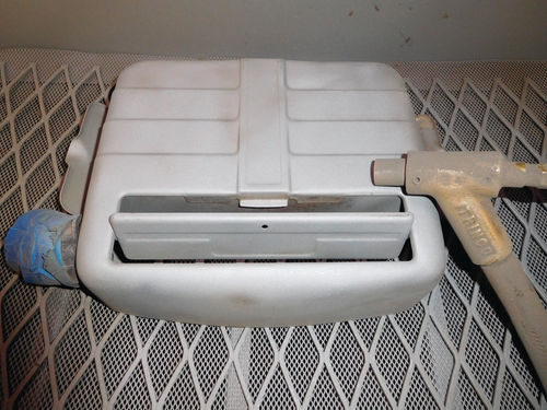
The heater we rebuilt came out of a 1953 Dodge B-4 pickup that’s undergoing a total restoration. The truck had about 20,000 miles on it when it was parked in a backyard in Stevens Point, Wisconsin, and a fence around the yard had no gate, so the truck remained inactive. The current owner had purchased it in the ’70s.

Given its low mileage, there was little mechanical wear on the Dodge, but years of sitting out had ruined things like the wooden bed and dictated the need for a complete restoration.

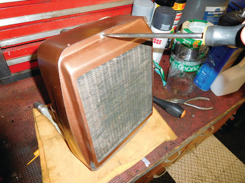
The factory-installed under-dash heater actually looked pretty good, but since the truck was not running before the restoration started, it was impossible to know the condition of the heater core, the functionality of the electrical wiring (the cosmetics were terrible) and the fan. In addition, the housing itself needed cosmetic work.

Taking It Step-By-Step

The following series of photos trace the work done to the heater. The photos cover the disassembly, testing, cosmetic refinishing and reassembly of the heater. As things turned out, we were lucky and all the parts of the system were reusable and there was no need for replacements.

In a nutshell, what we did was remove the Bakelite elbows that serve as air outlets on this model heater. Then we removed four small sheet metal screws from the top corners and lower sides of the front half (cover) of the housing. There also are two screws that protrude from the rear half and have small nuts on them. These also are removed.

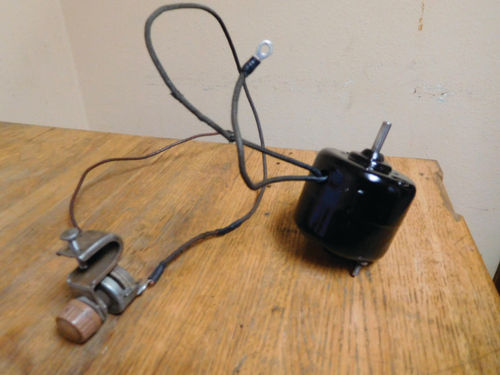
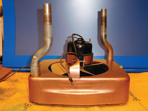
After removing the cover, we removed half of the circular bracket that holds the fan motor and fan in proper position in back of the heater core. Next we removed the electric motor, the fan which is mounted on the motor and the electrical wiring. The wiring was the original cloth braided stuff and had lots of breaks in the fabric wire covers. Not wanting to disassemble the motor to rewire everything, we repaired the old wires with shrink tubing. You will find reasonably priced shrink tubing kits at Harbor Freight (harborfreight.com).

The wires running to the motor were black, so we repaired them with black shrink tubing. That way the repaired wires will still match the color coding in the factory wiring diagrams. You cannot always get the right diameter tubing in a particular color, but we were lucky that we found small diameter black shrink tubing. This is plastic tubing that looks almost like a straw, but when you hit it with a heat gun it shrinks tight on the wire.

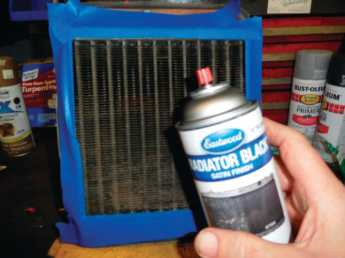
After fixing the wiring, we cleaned all the metal parts (housing panels, fan, motor) and blasted them with plastic beads in a media blast cabinet. We used either duct tape or magnetic plugs from Eastwood to keep the media from getting into any areas where we didn’t want it. That sounds easier than it is but it can be done.

We tested the operation of the electric motor by hooking the wires to a six-volt battery. The fan worked fine. If it didn’t, we would have taken it to Fondy Auto Electric in Appleton, Wisconsin, to get the motor rebuilt. We took the heater core to Al’s Radiator in New London, Wisconsin, where it took about two minutes to test it in a big tank and with a garden hose. It was perfect and there was no charge for the short test.

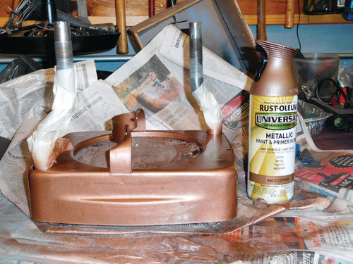
The final steps were to paint all the pieces and put everything back together. Again, that sounds easier than it is in real life. Getting 65-yearold sheet metal to fit just right takes patience. It’s easy to scrape new paint when sheet metal panels fit together with an overlap around the edges. Another tricky thing was getting the fan to spin it its opening without “tinging” on the edge of the opening. It was driving us crazy until we discovered that tightening or loosening the bracket around the motor actually adjusted its position in relationship to the opening. When you get it to the right tension, the fan doesn’t hit.

Now, follow along with us as we do the rebuild on these pages:

Parts Resource

John Geidl (Used Dodge Truck Parts)