
Repair a Back Glass Opening
The “Metal” Around This Glass Was Mainly Plastic Body Filler. Here’s How to Fix That Situation & Keep It Solid.
WHERE IS THE one place you can almost be guaranteed you’ll find rust on your ’60s project car? How about around the car’s back glass opening?
Aside from preventing the back glass from falling out, this opening is little more than a trap for dirt and moisture. It doesn’t take long for the moisture to turn the dirt into mud and the mud to turn the metal into rust. Before you know it, the rust has begun to spread and the telltale signs of bubbling and failing paint around the back glass stand as an omen that you may have a serious problem.
Of course, if you’re not sure all that bubbling paint is an indication the back glass opening on your ride has rusted out, just open the trunk and look for water on the floor pan.
Better yet, peel up the trunk floor mat and look for rust holes.
Searching for Solid Metal
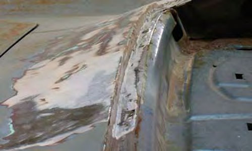
Or, maybe you can do like I did and remove the back glass and do a little probing. Yes, that’s a putty knife sticking through what should have been solid metal (Photo 1).
It was finding little things like this that prompted me to look deeper.
I had to remove some of the old paint and aging body filler found under that paint before the real condition of the back glass opening began to reveal itself (Photo 2). What you are seeing here is a problem that at first glance didn’t look all that bad. What makes it especially bad is that so far I haven’t found very much metal, just more body filler. More probing is needed.
A little more probing and a little time spent cutting away some of the rusted metal using a die grinder with a three inch cutoff wheel attached revealed the entire lower flange of the back glass opening was gone, rusted completely away (Photo 3). Furthermore, what you are seeing here is some creative work done many years ago using a lot of plastic body filler to fabricate a new flange. Don’t be surprised. This repair was probably made back when plastic body filler was first used to replace lead fillers. The thought back then, sometime in the early ’60s, was that plastic body filler could fix anything.
A Better Approach to the Situation
So, the question of the day is how do I fix this problem? To answer that I’ll back up to the beginning and start by removing the back glass without breaking it. To accomplish that removal task I have three options.
First, I could call my local automotive glass installer and have him remove the glass, which in many cases is a very good idea. This particular back glass is “soft set,” which means the glass was installed from the factory using a rubberized adhesive compound that acted to both hold the glass in place and to seal the glass to prevent moisture from penetrating into the car.
They referred to this glass installation method as “soft set” because the compound they used remained somewhat soft and pliable. At least it did for the first 10 to 20 years. Then it got hard, it cracked and started leaking. Having a professional cut this rock-hard stuff out is the best way I know to prevent breaking the glass.

Second, I could use a windshield knife to cut the glass out (Photo 4). This is a right-angled cutting blade set in a handle that is designed to allow the blade to reach under the glass and cut the “soft set” to free the glass. This method works pretty well if the “soft set” isn’t completely rock hard. The drawback to using this tool is that you can easily break the glass if you are not careful.
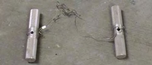
Third, and this is my glass removal tool of choice, is the cutting wire (Photo 5). This is a four-foot length of extremely thin yet strong wire with a handle attached at each end. (It’s available through Eastwood as part #40007.)
To use a cutting wire, I start by heating one end of the wire, using a small butane torch, until the wire begins to discolor from the heat. Then, using a pair of needle nose pliers to hold the hot wire, I force the heated end through the “soft set” material. I end up with one end of the wire inside the car and the other end outside the car. I then connect the handles to both ends of the wire and work the wire back and forth like a saw to cut through the “soft set” material to free the glass. This method works best with two people and will cut through “soft set” even if it is rock hard. The downside to this method is the same as with using the knife. You can break the glass if you are not careful. What’s considered careful? Just like using the knife, you must keep the wire, or knife blade for that matter, working parallel to the glass and never allow the wire or blade to push against the glass.
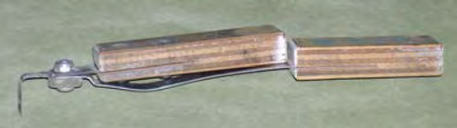
That is how to get the glass out, but this car also has stainless steel reveal moldings all around the back glass that must be removed first. To remove these moldings I use the tool shown in Photo 6. Made by Steck Manufacturing Co., part #21500, (Eastwood #52021C), this tool is designed to reach between the molding and the glass and unhook the retainer clips holding the moldings in place. Removing the moldings exposes the edge of the glass so the glass can be cut out and removed. Store all glass on its edge in a safe place. Never lay a glass flat. It might break.
Repairing the Metal
Now, let’s get back to the business of repairing this glass opening.
After pushing the putty knife through what should have been metal, I realized nothing back here was as it seemed and a wrong move could destroy everything. So I stopped and began to make up some replacement pieces for the glass opening flange while I still had something to use as a pattern.
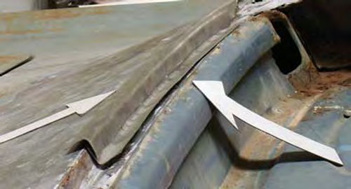
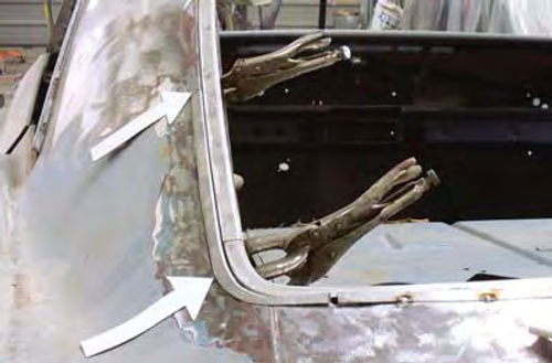
Notice a few things going on here (Photo 7). First, the plastic body filler flange is still intact. I haven’t taken the die grinder to it, not yet. That’s because I’m using this old flange to make sure I get the shape of the new flange correct.
Next, notice that the new flange I’ve made actually consists of two separate pieces of metal, with the outer top piece overlapping the inner piece. Finally, notice that the new flange extends only halfway across the width of the back glass opening.
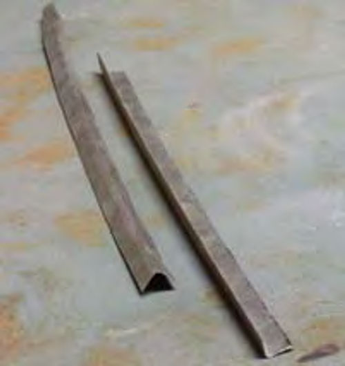
Let’s start with why I’m using two pieces of metal to make up the new flange (Photo 8). Notice that both pieces appear to be curved. They are, but what you can’t see is that the pieces of metal actually have compound curves. Each piece is bowed slightly, then arched perpendicular to the bow.
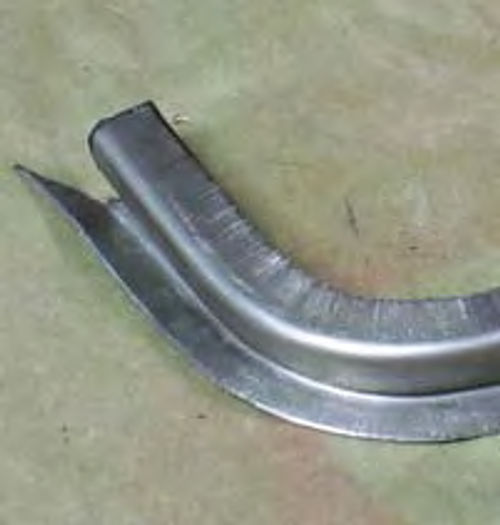
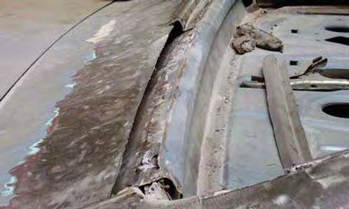
To get a better idea of how this opening is shaped, notice that the bottom flange is both curved from end to end and arched downward from the center outwards (Photo 9). In my shop it is impossible for me to bend a single strip of metal into the “Z” shape of the old flange and add both a curve and an arch to a single strip of metal to act as the replacement. Thus the need for cutting two separate strips of metal to make up the new flange.
What gauge metal am I using? In an area like this where I will be overlapping panels, shrinking and stretching metal,and forming curves and arches, I like to use 20-gauge steel. Each strip is cut from sheet stock and measures 11 ⁄2 inches wide by 26 inches long. Metal shears or a die grinder with a 3-inch cutoff wheel work great for cutting the metal.


Why cut the strips 26 inches long instead of cutting them long enough to extend the full width of the opening?
My sheet metal brake, used to make the 90-degree bends in the strips, will only handle 30-inch-long pieces of metal. Besides, working with only half of the back glass opening at a time lets me maintain the integrity of the opening by only cutting a portion of it out at a time. This method also ensures that I’m able to keep the opening size exactly correct. In other words, working in small increments equals greater control over the entire project.
With the two strips of metal cut and folded 90 degrees on the sheet metal brake, I can then go to the Eastwood Shrinker/Stretcher #28053 and put both a curve and an arch into each piece (Photo 10). For the result, go back to the two strips of metal shown in Photo 7. One strip of metal serves as the base of my flange and the other strip serves as the overlap piece that extends out onto the outer package tray panel.
Creating this part of the glass opening is pretty simple. The main thing is to be very careful when adding the curve and arch to the separate pieces. It doesn’t take much pressure on the Shrinker/Stretcher to bend this thin metal.
To arch the pieces I used the stretcher function on the Shrinker/Stretcher machine to stretch the vertical lips of both pieces. That action automatically causes the pieces to arch.
To put the curve into the pieces I switched to the shrinker function on the Shrinker/Stretcher machine to shrink the horizontal lip of each piece. That action automatically causes the pieces to curve a little. Not sure about all that? Get the machine and practice. Before long you will be forming tightly curved pieces like the ones in the next photo.
These are the two pieces for the left lower corner (Photo 11). A good tip is that it is much easier to form this corner from long strips of metal. Once curved, then slightly arched, the pieces can be individually fit to the opening with the excess length being trimmed off as necessary.
Here are all four pieces of the new glass opening flange for the left-hand side in place on the car (Photo 12). Notice that I have only tack welded the lower flange and haven’t welded the side pieces at all. I need the bottom section somewhat rigid in order to fit the corner pieces. How do I know when the pieces are fitting correctly? Check out Photo 13. Look closely and you can see that I have temporarily installed the reveal moldings inside the opening. I could spend all day measuring and checking, but the moldings only take a moment to install and they can tell me instantly if my new flange is the right size and shape.
The Welding Strategy

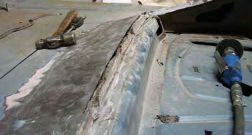
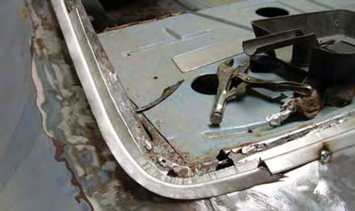
Moving to the right side of the car you can see I have begun to cut out the rusted metal (Photo 14) in preparation for repeating the same type of flange construction I did on the left side. Looking back to the left side, notice that I spot welded the top flange piece to the inner piece. This area of the flange doesn’t need a continuous weld. Once all of the body work around this opening has been accomplished, I’ll run a bead of seam sealer along the line where the two pieces meet.
A look at the right side with the new flange pieces in place (Photo 15). If you take anything at all away from here at this point, it should be that nothing on this side of the car has been welded solid. I’ve made only those welds that are necessary to secure the pieces in place until I can test fit the glass. Only after I know for certain the glass will fit in my new opening will I weld the new flanges solid, and only on the outside of the car. The inside areas will be spot welded.
Why weld the outside pieces solid? I don’t like the thought of leaving open gaps that might offer moisture a point of entry underneath the plastic body filler I’ll use to smooth this repair.
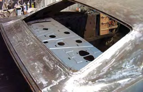
So what does my rebuilt back glass opening look like? Take a look at Photo 16. I spent a little time with a die grinder and a three-inch cutoff wheel smoothing welds then went back over the repair looking for any holes I might have missed with the initial welding. I welded those holes shut, ground a little more and the result is what you see here. When I’ve moved a little farther into this restoration I’ll coat this repair with epoxy then smooth everything with a little plastic body filler.
And what about replacing the reveal molding clips? I’ll order new ones from one of the vintage Chevy parts suppliers and install them using sheet metal screws after the car has been painted.
Got a question? Send it along.
Resources
LPL Body Works, LLC
5815 Contented Lane
Amarillo, TX 79109
Body and paint repair DVDs
Eastwood Company
263 Shoemaker Rd.
Pottstown, PA 19464
Steck Manufacturing Co., Inc.
1115 S. Broadway St.
Dayton, OH 45408
Auto body tools and equipment


