Installing Shop Air Lines
Here’s How to Pick an Air Compressor, Route the Supply Lines & Make Sure You’re Using Properly Filtered Air.
A FEW YEARS ago I did an article on plumbing a garage shop for compressed air. To this day I still get questions concerning what size air compressor is best for a particular application, how to go about routing air lines, and how the air coming from that compressor and flowing through those air lines should be filtered. I think it’s time to address these issues again and bring you up to date with some new methods and new products.
Look for the CFM
When shopping for an air compressor, whether for the garage or for the shop, the key information you are seeking is the CFM (cubic feet per minute) the compressor is capable of producing. The CFM output of your compressor determines what air tools can be efficiently used with that compressor.
Forget about PSI (pounds per square inch). Most hand-operated air tools are designed to work best at or below 90 PSI. You won’t find very many air compressors that don’t crank out at least 90 PSI. As a matter of fact, most air compressors that use a storage tank produce more than 90 PSI. Generally you will find this type of compressor will have an automatic cutoff switch that turns the compressor off when it reaches 120 PSI.
So for now let’s look past the PSI rating and get to the heart of what an air compressor is designed to do. Just what is that? An air compressor is designed to provide airflow, which is measured in cubic feet per minute, better known as CFM.
Here’s an example. If I plug an orbital sander into an air hose with a PSI gauge attached to the tool inlet, more than likely the reading will be 90 PSI.
So, what happened to the 120 PSI most compressors crank out before cutting off? That’s the rating coming straight out of the compressor. The first stop after the compressor should be the air filters. Once the air is filtered, the PSI rating coming out of the filtering system should be adjusted down to 90 PSI using a regulator.
Now that I have the air system regulated down to the 90 PSI recommended by most air tool manufacturers once the air leaves the filters and travels down the air lines, I can get back to the gauge reading on the orbital sander.

Just because the gauge reads 90 PSI doesn’t mean the tool is functioning. It isn’t. At least not until I squeeze the trigger and start that 90 PSI of air pressure moving through the sander. That’s when the PSI at the inlet becomes less important and the cubic feet of air moving through the tool becomes paramount. No air movement, no tool operation. To get the palm sander to work there must be air flowing through the sander.
Not only does there need to be air flowing through the tool, there needs to be a lot of air flowing through this tool. A quick look at the specifications for the palm sander and I know this tool requires 11 CFM @ 90 PSI for maximum efficiency. That’s a lot of air flowing at a very high rate of speed. Compare the palm sander to a typical HVLP paint spray gun and you will find that on the high side that spray gun will require 12 CFM to operate at maximum efficiency, but needs only 28 PSI when delivering that 12 CFM. That’s still a lot of airflow, but at a much lower speed and pressure. How confusing is that? Let’s see if I can clear the air.
A physics formula exists out in the world of mathematical wizards to calculate the change in CFM when the PSI is altered: ACFM = SCFM*( (Pstd - PVpstd*RHstd)/(P1*RH1)(*(T1/Tstd) Where Pstd = 14.696 psia, Tstd = 60 deg. F and RHstd = 0%.
To be correctly used, this formula needs things like internal pipe area, air density, and air flow requirements in order to come up with a usable result for a given scenario. But change the scenario, meaning exchanging one tool for another and the formula is no longer valid and will have to be recalculated.
What am I getting at?
Forget the formula; forget trying to figure out pipe size, relative humidity and tool requirements. Choose an air compressor that is rated to produce the maximum required CFM output for the tools you will be using. In my example, the palm sander requires 11 CFM at 90 PSI so that is the compressor I need, one that is rated to handle this CFM requirement.
What that does is ensure that every other pneumatic tool I own, including spray guns, will operate efficiently with this compressor. Yes, I may have just copped out on precisely figuring out which compressor is best for a given application, but believe me, this is the easiest and the best way to determine which compressor is right for your shop.
All right, I will give you a little more backwoods information where CFM and PSI are concerned. Let’s go back once more to the palm sander that needs 11 CFM @ 90 PSI. If my compressor is rated to produce 12 CFM at 120 PSI (5 hp and up compressors often are) then I know from actually having calculated the Physics formula for two different scenarios that the ratio between CFM and PSI narrows as the PSI requirements come down. For example, with the air filters regulated down to 90 PSI on their output side I may actually have 13 to 14 CFM available at 90 PSI, more than enough to run the palm sander. If I exchange the palm sander for a pneumatic tool that needs 40 PSI at the input I may actually have 14 to 15 CFM available at the tool. See the trend? As a given tool’s PSI requirements decrease, the CFM available for that tool increases as long as the potential PSI (90 PSI at the regulator output) remains constant.
From the Compressor to the Tool
In the old days we used black steel pipe, the same stuff used to route natural gas lines throughout a structure, as air lines. It worked great, but was a pain to route, had a tendency to hold moisture, and eventually rusted from the inside out.
Then came PVC. We routed this stuff in the “big shop” several years ago and thought we would never again have an air line problem. But one day a line broke at one of the connections and the fear of PVC swept through the shop like body filler dust through a paint filter. The swap back to black pipe was costly. We left the old PVC pipe in the rafters as a reminder of our flawed thinking.
The good news is that today we have something even better than black pipe— flexible tubing. Made from nylon, this 3/8-inch ID, 150-PSI-rated tubing can be easily routed anywhere throughout the shop as it can be bent and curved where needed. That means fewer connections, as in no more elbows to bend around corners, and fewer connections equates to fewer opportunities for leaks.
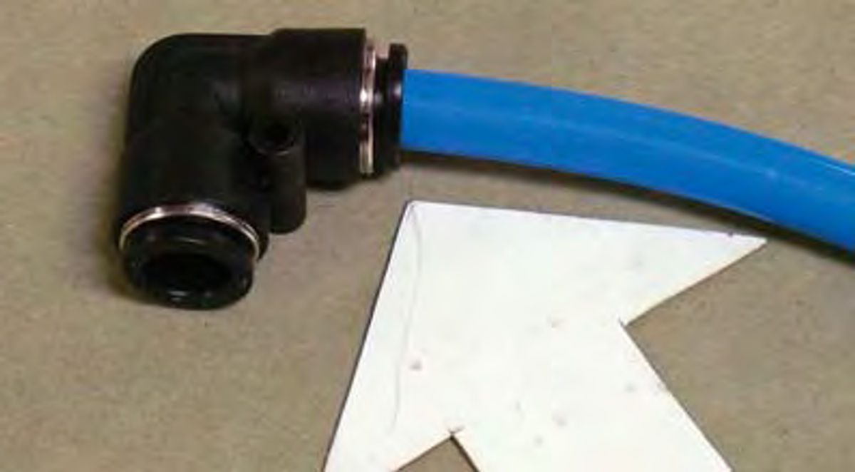
Speaking of leaks, this nylon tubing uses unique leak-proof connections that let the installer instantly make a fitting by simply pushing the tubing into the connector. No compression rings, no cross threading the couplers, and no loose pipe (Photo 1).
Where do you find this stuff? Try Eastwood. They have put together a complete kit called the Garage Air Kit #51057 that contains 100 feet of 3/8-inch ID nylon tubing, an assortment of fittings and attachments, one dual-output compressed air manifold, two single-output compressed air manifolds, and a handy tubing cutter. Like the name implies, this kit is designed to plumb a typical two-car garage (Photo 2).
Plumbing the Garage
I start by determining the best spot to locate the compressor. I don’t like having these noisy monstrosities inside the garage itself, but sometimes there is no alternative. My preference is to locate the compressor in an out building, such as a storage shed, and pipe the air into the garage much the same way that natural gas is piped into a structure.
Natural gas is piped underground to the side of a building where the inlet pipe comes up and enters the building. This pipe is usually insulated where it exits the ground to prevent condensation problems.
If the compressor has to be located inside the garage, pick an out-of-the-way corner and mount the compressor on rubber foot pads to dampen the vibration going into the floor.
Whether stationed inside or outside, the compressor should be bolted to the floor to prevent it from moving.
How do you bolt the unit to a concrete floor? Visit your local home improvement center and tell them you need to bolt something to a concrete floor. They stock a drill bit capable of drilling through concrete, metal inserts to hammer into the drilled holes, and bolts specifically designed to lock into the metal inserts and hold the compressor solid.
What about the rubber foot pads? Those will come with the compressor.
Setting Up the Garage Air System
The next question is where do you want air? I look at a two-car garage as a two-stall shop. It’s a shop that may have to be shared with the wife’s grocery getter, but it’s a shop nonetheless. So my preference is to have at least three compressed air drop points where I can attach an air hose. That is, one at the front of the garage and one on either side wall.
To deliver air to the output manifolds, the kit we’re using contains an assortment of fittings and tees that offer a lot of options for routing the tubing. Having a hundred feet of tubing doesn’t hurt matters either.
The air lines can be routed along the walls, up and over the ceiling, or even down on the floor. Whichever way works best for a particular application, the kit comes with everything needed to get the job done.
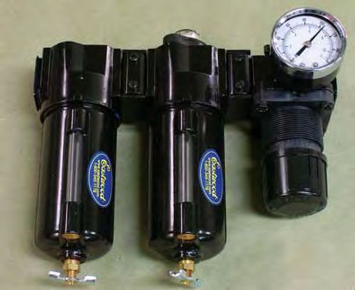
What the system doesn’t include is an air filter to mount between the compressor and the first output manifold. For that I selected the Two Stage Air Filter/Regulator System #51106 from Eastwood. This system uses 3/8-inch NPT (National Pipe Thread) fittings, compatible with the Garage Air Kit fittings, a moisture separator, coalescing oil filter, 150 PSI regulator, and manual shutoff valve (Photo 3).
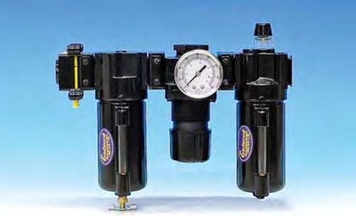
Having a built-in oil filter, this two stage system is designed with the paint shop in mind. Should your thinking be more along the lines of doing all of the mechanical work on your ride and none of the paint work, then consider the EW Lubricator/Filter/Regulator System #20601 (Photo 4). This unit automatically provides lubrication to all of your pneumatic tools. No more adding a few drops of oil to each of the tools before you begin work. But don’t put this unit into a system designated for spray painting. You certainly won’t appreciate having to sand out all the fisheye contamination that would be caused by the lubricated air.
Time for Some Wall Mounting
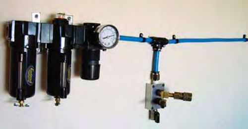
Since everything keys off of the air filtering system, that is where I’ll start. I temporarily mounted the filters on the wall, because at this point all I’m doing is determining the best locations to mount things, and routed a section of tubing out to one of the tee connectors provided in the kit (Photo 5).
The tee connector lets me add a drop point for the dual-output manifold before continuing the tubing on across the wall, around the corner and down to a point about midway along the length of the adjacent shop wall.
Even though I’ve only temporarily mounted the filters on the wall, I made sure to securely attach the tubing and the dual-output manifold to the wall. I can’t take securing these items to the wall lightly. It doesn’t take much effort to jerk the manifold off of the wall if it isn’t firmly secured. I used 3-inch-long drywall screws to secure the manifold and tubing to the studs behind the wallboard.
Can’t find a stud? In that case a return trip to the home improvement center is in order. Ask for enough “wing bolts” to complete the job. What’s a “wing bolt?” In this case, it is a #10 bolt, two inches long with a spring-loaded and hinged “T” on the end. The hinged T is pushed through the wall via a 3/8-inch hole drilled previously, the springs on the T open the hinges on the T, preventing the mechanism from being pulled back through the wall. The bolt is then tightened for a very secure wall attachment.
As for where to mount the individual components of this air system, my choice is to place the outlet manifolds near the center of the wall and roughly four feet up from the floor. Four feet is also a convenient height for the air filters as it makes servicing the unit much easier.
If there is one thing to remember about the placement and servicing of these air filters, it is that the filters will accumulate water and that water should not be allowed to drain in a location where it might seep under the walls and into the house.
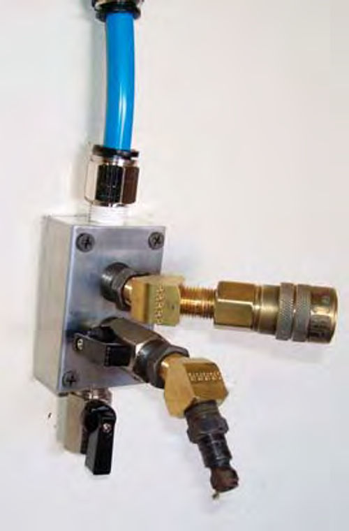
Notice that I added a moisture drain to the bottom of this first output manifold (Photo 6). Some moisture, primarily due to condensation, will accumulate in the lines. This petcock will allow me to drain that moisture from the system.
Then notice that I added a female connector to the top output and a male connector with a cutoff valve to the bottom output on the manifold. All paint shops should have an air hose dedicated for use only when spray painting. To ensure this hose is never used for any other purpose, I installed female couplers on both ends of the hose. It can only be plugged into the male connector on this manifold, which hopefully will remind the user of why the hose and manifold are set up in that configuration.
On to the Other Manifolds
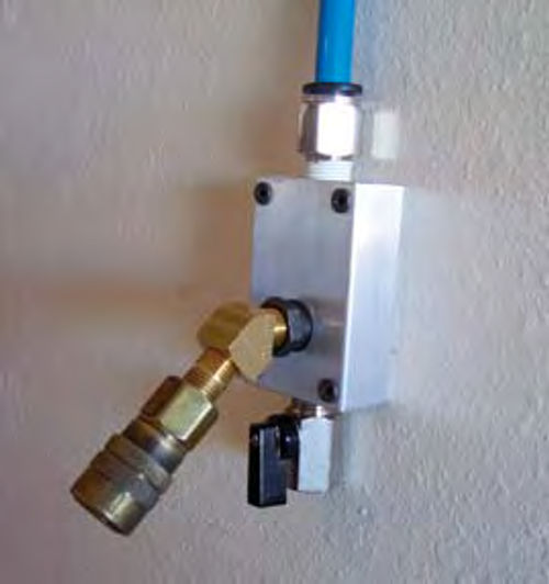
That leaves me with the two single output manifolds. Each one will serve as an end point for my air system and be mounted on either side wall of the garage (Photo 7).
To get air to the single-output manifolds, the nylon tubing is routed along the wall about four feet off of the floor until it reaches the first manifold. Before connecting the tubing to that manifold, I added another tee and branched the tubing off so that it went up and across the ceiling just forward of the garage door opener and back down to the second single-output manifold.
Since the tubing will bend easily, I can dispense with adding an elbow where the tubing bends to move across the ceiling and instead use the fasteners supplied in the kit to allow the tubing to make a gentle bend at that point.
Attaching Tubing to the Fittings
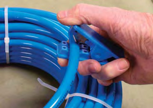
As I showed you in Photo 1, this system uses a quick disconnect coupling system. For this system to work efficiently, use the cutter that comes with the tubing to make your cuts (Photo 8). A hacksaw or other cutting instruments can leave the end of the tubing frayed and jagged, which can impair the fit and result in minor leaks.
Simply push the end of the tubing firmly into the fitting until it seats. Then gently pull on the tubing to make certain you have a positive seal. You’ll know you have a good seal when the tubing won’t pull out of the fitting.
Need to swap fittings or add a length of tubing? Grasp the fitting firmly, then push the tubing into the fitting while pressing on the release ring at the end of the fitting. When the release ring seats against the fitting housing, pull the tubing free. Release the ring and the fitting is ready for use again.
Tips for the Project and Afterward
•Be sure to secure all of the manifolds to the wall. As mentioned earlier, I use three-inch-long drywall screws for this type of procedure, making sure the screws found the 2x4 studs behind the wallboard.
•Use the supplied retainers to secure the nylon tubing to the wall and ceiling. Do not allow the tubing to have any unsightly sags. It just doesn’t look good, and it reflects poorly on the person who did the installation.
•Securely mount the filters to the wall. More drywall screws will do the trick.
•When testing the air system for the first time, open the moisture drains on all of the outlet manifolds to flush out any particles that might be in the tubing. After flushing, close the drains and check the system for leaks.
•After the floor has been swept at the end of the day, be sure to turn off the compressor and close the outlet valve on the filtering system. Rubber air hoses break, but they never break during the day while you are working. They only break when you’re away.
•Speaking of hoses, I recommend rubber hoses. Avoid those stiff poly-something hoses that never want to lay flat on the floor and get stiffer by the minute as the temperature drops. You might even consider darkening the door to the local home improvement center and purchasing three of those “hang on the wall” water hose hangers. It’s a good way to keep air hoses off of the floor when not in use.
•Finally, what do you do with any leftover tubing? The owner of the garage, excuse me, but the addition of an air system has elevated this garage to “man cave” status, came up with the idea of adding water outlets to the side walls to facilitate wet sanding.
We connected the leftover tubing to a faucet, routed it next to the air line tubing, added additional faucets at the ends, and presto, we had outlets for connecting the Wet Sanding Sprayer featured in the October, ’08 issue (Larry’s Product Reports).
Got a question? Send it along.
Resources
LPL Body Works, LLC
5815 Contented Lane
Amarillo, TX 79109
Paint and body repair DVDs
Eastwood Company
263 Shoemaker Rd.
Pottstown, PA 19464
Automotive tools and supplies


