Installing a Modern Sound System
There Are Totally Modern Systems Designed for Vintage Vehicles. Join Us as We Wire One Into a 1955 Chevrolet.
ONE OF THE great pleasures of owning a classic ride is rolling down the open road in a great set of wheels while listening to great music. Follow along this month as we upgrade the audio system in our project ’55 Chevy. We will be installing a RetroSound Model One C (Chrome face) Stereo, which is designed with the look and fit of a factory system. It has great features including front and rear auxiliary inputs that allow use of iPod and MP3 digital music players, a remote control and a digital AF/FM tuner with Radio Data System (RDS), which shows song titles and artist information broadcast from the radio station. It also has a really slick remote mountable interface unit that lets you play digital music from a USB memory stick or an SD memory card (like what’s used in digital cameras). The remote interface unit can be mounted in a glove box, a console or any number of other discrete locations.
The Retro Sound was designed specifically for the old car hobby, and has great audio quality and many modern features. Itwillfit a wide variety of vintage American, European and Japanese cars. It has a very compact case design, and its “InfiniMount”systemallowsthecontrolshafts to be mounted in any configuration, or at any angle. It even fits applications with both shafts on the same side. This allows installation in many difficult applications that up to now could not be outfitted with an aftermarket audio system.

Out With the Old
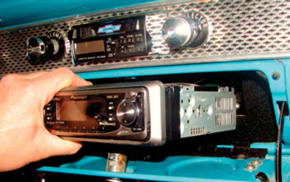
The first step is to remove all of the existing audio equipment. Our project car was outfitted with two stereo units— a dead aftermarket radio installed in the factory location in the dash, and a working unit that was hidden in the glove box. The new unit will replace both of the old ones, giving us much better sound, and also allows us to use the glove box again. No more hiding the registration and insurance papers under the driver’s seat!
The old hidden unit was removed from inside the glove box, the glove box door was removed and carefully set aside, and the dash-mounted radio unit was removed (Photos 1 & 2). While removing both of the old units, I carefully disconnected and labeled all of the old wires. Even though I planned on replacing most of the wiring, it is still handy to have the old wires labeled to keep track during the job. The only wires I Did not replace were the pre-amplified signal wires for a remote amplifier that is installed in the trunk, since I replaced those wires last year at the same time I rebuilt the body wiring harness(AR June & July 2011).
In With the New
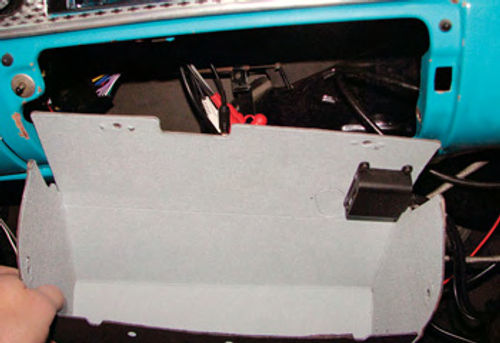
In order to get that factory look, there are many different mounting kits to install this audio equipment into many factory applications. Some installations use bezels, like our Bel Air (Photo 3). The bezel fits from the back of the dash to adapt the audio equipment to the factory hole. Other applications use a faceplate to cover the dash hole from the front.
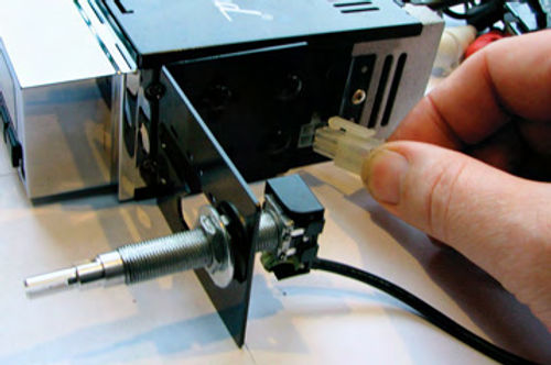
With the new unit sitting on a workbench, we installed the InfiniMount shaft brackets to the chassis, leaving the screws loose to allow adjustment as needed for proper mounting. Next, we installed the volume and tuning shafts with the same spacing as the original dash-mounted unit. The RetroSound installation instructions are pretty good overall, but this area was vague and could have used more explanation. Photo 4 shows the proper assembly sequence of the various nuts and washers needed to mount the shafts. While the width of the shafts was set to be the same as the unit we removed, the depth of the shafts was set to an intermediate position. Once everything was mounted, the shafts were plugged into the chassis and the unit was ready for installation (Photo 5).
Getting a proper fit in the dash is not difficult, but it can be time-consuming. There is no magic—just take your time and trial fit as many times as it takes to get the adjustments just right. It requires a lot of trial and error to get proper gaps and the knobs at the proper depth. I did not count the number of times I trial fit the unit until I was happy, but I would guess about a dozen. I don’t feel bad about that—it’s better to take the time now to make it look right than have to look at a sloppy installation for years to come.


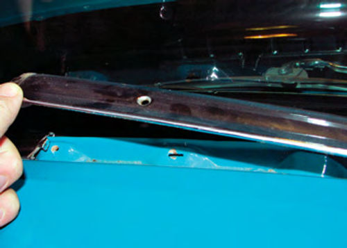
With the unit in place in the dash, the last mounting task was to install a strap to hold up the back. The strap bolts to the underside of the dash underneath the windshield garnish molding. First I removed the garnish molding to access the screw head (Photo 6), then I removed the existing strap and screw. I used a piece of coat hanger wire to mock up the new strap and make sure the bend would be in the right place. I also intended to use the mounting screw as an electrical ground, so I took a few extra minutes to properly prepare the underside of the dash. I started by sanding the bottom of the dash with 220-grit sandpaper to remove surface rust and get to clean shiny steel around the screw hole. Next, I applied a thin coating of dielectric grease to the cleaned area. I installed the screw from the top and then applied a star washer, the new L-bracket, another star washer, a ring terminal with a short ground wire attached, then a nut. I finished the installation by applying a light coating of clear coat to the bottom of the dash to discourage surface rust from forming at the ground (Photo 7).
Wiring the New Unit
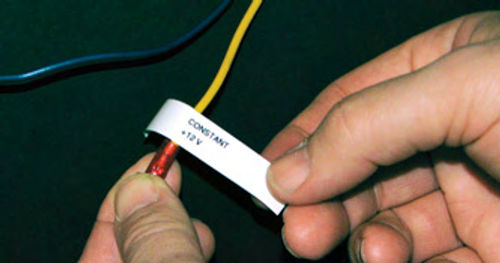
Now that we have the new audio equipment properly mounted, it’s time to wire it up. The new unit is equipped with an ISO plug, which contains one plug for the power wires and another plug for the speaker outputs. This is a nice feature because it allows the installer to create a nice and tidy wiring harness and to be able to easily remove or install the audio unit or wiring harness later for other under dash service if required. The four wires I needed in the power plug harness are 1) a constant power source, 2) a switched power source that turns on with the key, 3) a ground wire, and 4) a remote amplifier power-on signal.
I started by splicing extension wires into the ISO plug for the signals that I needed (Photo 8). I used wires that were the same color as the RetroSound wiring harness. This is important for future maintenance or troubleshooting. It is significantly harder to troubleshoot a wiring harness where the wires change colors from one end to the other. It should be noted that the wires in the power plug are not all the same wire gauge (diameter),so you need to ensure that the wire extensions match the plug. If you can’t find wire of the same gauge, go one size larger in diameter (smaller gauge number).
One wire that I did not need was for a power antenna control, so I cut off the end of the wire and sealed it off by folding the end back on itself, then covering the end with heat shrink tubing. It’s dangerous to leave unused wires uncovered under the dash, as they can lead to a short circuit.


Once the wires were extended, I test fit the harness under the dash to determine the proper final lengths for each wire. I routed the constant and switched power wires to the fuse block. I routed the remote amplifier power wire to the left side kick panel, and added a disconnect plug to allow the wire to be disconnected if needed without having to cut and splice. The ground wire was connected to the new under dash ground using a disconnect plug. Each wire was then cut and a proper terminal was crimped into the end. The connections at the fuse block use female spade terminals, which make connection easy.
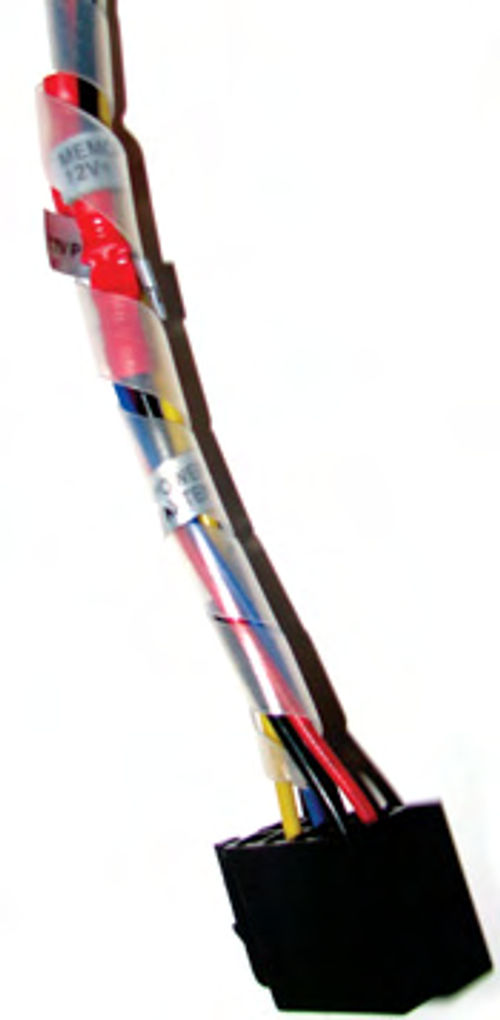
Finally, I wrapped the wires together into a nice-looking wiring harness using a spiral wire wrap (Photo 9). That keeps the wires neat under the dash, and helps to protect them. I finished off the wiring harness by making labels for each wire with my label maker, then installed and connected the wiring harness (Photo 10).
A New Dual-Channel Speaker
Our ’55 Chevrolet was originally equipped with a single speaker mounted in the dash on the passenger’s side and a single speaker in the parcel shelf in the back seat. The car had previously been upgraded with four speakers—one in the bottom of each front door and two in the rear parcel shelf. They were wired to a remote amplifier in the trunk. That part of the audio system worked well, so I did not change it.
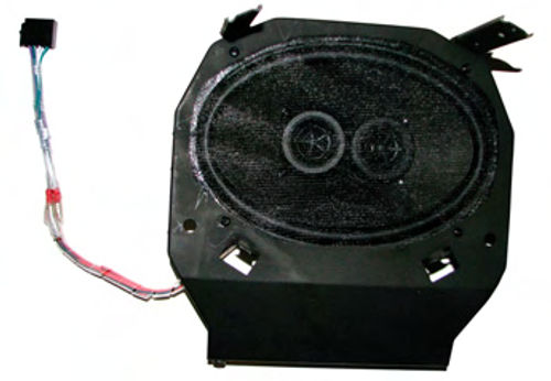
However, I wanted to install a speaker into the stock dashboard location in addition to the four speakers already in the car. With early vehicles adding two speakers in a location that originally came with a single mono speaker is a problem. But several audio equipment manufacturers have developed speakers to address those installation problems. I chose to use a clever dual channel speaker, which is a single speaker designed to fit into the stock 6 x 9 location. This speaker has two separate speaker coils built in, for true stereo sound from a single location. One coil is driven by each of the front speaker signals.
I modified the speaker mounting bracket by cutting out the center webbing, since it prevented the speaker from fully seating, then I mounted the speaker into the bracket. I created a speaker wiring harness that connected to the ISO plug on the stereo unit, and overwrapped it with the spiral wrap (Photo 11). The speaker and bracket assembly were installed back into the stock dash location.
Installing the Remote Interface Unit
With everything installed and properly wired, I turned my attention to the remote interface unit.Many folks mount these inside the console or other convenient but discrete locations in their ride. On Project’55, I chose to mount it to the top of the glove box. I purchased a new glove box liner and test fit it and the remote interface in the car. Once I selected my location, I used a scratch awl to poke holes in the liner material, then used screws and large washers on the back side to hold everything in place. I installed the glove box liner back into the dash and then connected the remote interface wires to the stereo unit (Photo 12).
Reassembly and Testing
The preamplifier signal cables and the antenna cable were connected, and the wiring was all tidied into place using clamps and zip ties where needed. The glove box door was reinstalled on its hinge and properly adjusted; then it was time to try out the new system.
With great anticipation, I held my breath and turned it on. The results were…disappointing. The display showed gibberish and the unit would not turn on (Photo 13).
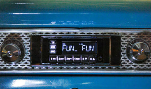
Before panicking, I carefully rechecked all the connections and tested voltages using my digital voltmeter. Between the RetroSound website and my voltmeter, I was able to identify the problem fairly quickly. The constant power circuit in the fuse panel showed 12 volts with everything turned off, but with the system turned on the voltage at the fuse panel was very low. The cause of this problem was some light corrosion where the fuse plugged into the panel. The resistance prevented adequate current flow to the radio. I spent a few minutes cleaning all the contacts with 320-grit sandpaper and a dab of dielectric grease, which restored the power. I tried again, and the results were…impressive! The audio system sounds terrific and it has many great features (Photo 14).

And The Verdict Is…
Installation of the RetroSound Model One in Project 55 was easy, and the new audio equipment fits well and looks like a factory installation.
But how does it sound? The audio sound quality is impressive and it is easy to use. I can now plug my iPod directly to the unit, as well as listen to the radio or digital music I recorded onto a flash drive.
Now, as long as there’s no snow to contend with, I will be rolling down the highway listening to my new tunes. And I will be easy to spot—look for the guy with the ear-to-ear grin!
Resources
Retro Manufacturing LLC
RetroSound USA
5785 Waco St.
Chino, CA 91710
Retro Manufacturing also has another division,
RetroBelt USA, that specializes in 2-point lap
belts and 3- or 4-point lap & shoulder belts for
vintagecars. They are at the same phone number or visit retrobeltusa.com
Custom Auto Sound
1030 W. Williamson Ave.
Fullerton CA 92833


