Back to the Bump Steer
An Article on the Subject Brought Reader Feedback and Questions. So We Gave Them to the Author for Research & Replies.
GREAT ARTICLE ON the subject of “Bump Steer” in the August issue. I don’t have much experience on front end modification, but I have an observation and a question. The drawing in the article seems to show that a line drawn through the lower control arm pivot points would travel right to the location of the inner tie rod ends (when the steering is centered).
This would make its up-and-down travel arc match that of the wheel. Anything else would seem to produce bump steer. Would that be a good rule of thumb as well as the many such rules offered by the article?
This brings to mind the many rack steering setups I have seen added to older cars. Their racks tend to have wide-set inner tie rod joints due to the rack mechanism in the center. This would seem to conflict with any such “rule” as above.
Can a control arm and a tie rod travel in different arcs without bump steer? Consequently, can rack steering always be a good match for older cars? I’d be interested in any more-knowledgeable opinion.
Mike Siney Via email
Mike, BINGO! You hit a real bullseye. And I love your observations and questions! You hit the gist of the whole issue of bump steer*. Plus you gave me a sharp pang of humility with your detailed reading of the article. You sure sent me back to the books, the shop, the drawing board and to consult my friend, a real expert in such matters.
(* Background: I define “bump steer” as the dynamic change in toe (tire rotating around the steering axis as it would when there is steering-wheel input) as the tire/wheel assembly moves through its full suspension travel up and down. We usually look just at one wheel but it’s definitely a two-wheel issue as well.
I want to give you short answers but first I think it’s important to mention some very basic items, just in case. Then after the short answers we can dive into some details.)
And a disclaimer (another one — or two): I’ll try to make sure that all the principles are presented as accurately as I can as I’m sharing experience and good lessons I’ve picked up over the years through work in the auto industry and automotive hobbies. And since I look at these topics more in terms of their application rather than real science, I tend to use common language and perspective more than someone who made a career specifically in suspension design.
Also, I’ll shoot for perfection and the perfect condition of the parts involved; but perfection just doesn’t happen in real life. Bushings squish and some parts flex a little during normal function and there are design and production compromises made very frequently. And some of those things are just too small in their influence to make much bother about, so I choose to skip them. But the rules and concepts are the real priority so I do my very best to respect them completely.
Regarding a rule of thumb that the wheel and tie-rod ends follow the same arcs: Yes, definitely. Also, the inner tie rod end lined up with the LCA pivot bar is definitely the ideal condition; you spotted the key principle, indeed. Moving off that line can lead to bump steer. “Similar” arcs will work but there will be some degree of bump steer.
Here’s a good spot to mention those compromises again. You’ll see in the included illustrations as well as on your own car that tie rods and control arms (along with the other components) can vary from those perfect conditions. And even though I did and will continue to stress that small variations can be significant, we’re still dealing with varying degrees of good and bad for bump steer.
Can rack steering always be a good match for older cars? Not always but likely sometimes (sounds too much like probably + maybe but that’s the best I can do), with details below.
Now be warned that we’re both wading into the deep end of the bump steer details pool. When we get to the transplanting of racks for gears then we’ll need to consider real steering geometry design.
I was afraid the illustration in the article wouldn’t be clear enough. I’m glad that you were able to see the detail for LCA (lower control arm) to tie-rod relationship in it.
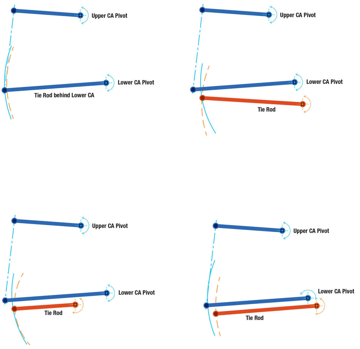
If the LCA pivot points directly at the inner t/rod end (centered steering wheel) as it looks in the article then that’s kind of the “perfect case.” This includes that, within fairly practical limits, the inner t/r ends really like to be on a plane that includes both the right-hand and left-hand side LCA pivot bars. But that’s pretty tough to visualize or measure even in a very good shop. A good, simple visualization of this is three dots on one line; one dot is fixed to be a center of the arc (LCA pivot lined up with the inner t/r joint), the farthest dot is the outside arc (this is the LCA ball-joint or trunnion of a kingpin knuckle), and the third dot is the outer t/r joint and it wants the t/r to be exactly the same length as the LCA or at least very close to it (if the t/r gets shorter then it will start affecting other considerations like the Ackerman effect, that is, the difference in turn radius between the front tires; steering ratio of steering-wheel to knuckle, and turning circle of the car). If that’s not clear, hang with me and check the next comment and here’s a sketch of what I’m saying in Illustration #1. The real, bedrock, working rule needs to be that the LCA (centerline during movement/swing) needs to be parallel and close to the tie rod (in all views) and the LCA and tie rod need to be of the same length. Requiring them to be parallel will then include the ends being at acceptable up/down and fore/ aft locations and the same length should cover the in/out location of the ends.
So, back to your question/comments. The LCA pivot pointing to the t/rod end is perfection but not required as long as you keep the compromises tightly under control (and designers compensate where they can). Here are more sketches to try to help show these issues and deviations from perfect.
Ill. #1. LCA and Tie Rod Perfectly Aligned.
Ill. #2. Tie Rod Inner Pivot Too Low.
Ill. #3. Tie Rod Too Short.
Let me just stop here to reinforce the priorities: up/down misalignment of any one tie rod joint is the most troublesome (Ill. #2). Tie rod length is also significant (Ill. #3).
As for the LCA and t/r traveling in different/not similar arcs without producing bump steer, no. Here’s a sketch of a “similar” location of the t/r (Ill. #4). Here the t/r is lower but still parallel to the LCA; the big difference is the t/r inner joint is away from the LCA pivot centerline. I hope you can see that the arcs are no longer parallel but the difference isn’t as bad as the other examples of bad locations shown above.
Ill. #4. LCA and Tie Rod Aligned Similarly But Not Perfect. (This will cause some bump steer, be careful.)
So, what’s the acid test of how bad is bad? The only good way to tell is to check the “toe pattern” on the car. That is, measure the changes in how a wheel moves in the “steering” direction as it travels through its range of vertical motion. Perfection is a straight, vertical line; no toe change. If it stays within about 1 ⁄32- inch of that perfect line you’ll be good. Up to 1 ⁄16-inch either way, consider making corrections. But if it’s more you’ll be well-advised to fix it right away. There are several good tutorials on how to check bump steer as well as help you identify which parts need attention. The Mopar books noted in the article seemed very clear and easy to follow when I used them for our projects. I’m sure there are other books and also good websites as well as good computer programs you can purchase that will do the math as well as show what parts may need attention.
About the Rack Steering Question…
Putting a rack steering gear on an older car? Interesting indeed! (And I just heard some rumblings of aftermarket “electric” power racks becoming available. These would be nice, neat, oil free installations!) Most older cars have (had) a big, in-line engine smack where a rack should go and in addition to that a cross-member in front of the engine. Modern cars have several advantages like smaller engines, V-engines sometimes, transverse engines sometimes, and the engine is generally way farther forward in the vehicle than the oldies. (“Cab forward” often pushes the engine completely forward of the front “axle”.)
There are probably cases where a rack installation is impossible due to the steering and engine compartment configuration. Older cars sometimes had a bell crank instead of pitman arms or racks — those could either be very tough for sure or, if you used a rack with a center output they could be quite good plus fairly easy to do. That center output rack might work well with the old system shown in the article. It sure appears that the inner t/r joints are close enough together to make it a likely fit. The other concern would be a solid, well-located mounting for the rack.
In general, however, if there’s a will, there’s a way. But significant modifications may be needed. As soon as the modification route is chosen it will actually require a total geometry study of the car. Again, not that shade tree mechanics haven’t done it in the past, but a one-of-a-kind steering system requires that every part that connects wheel to frame to steering system comes into the equation and now the full motion of the wheels (both of them) needs to be considered. There are just a whole lot of parts and a whole lot of positions to consider. That’s why automakers used to use a big drafting room full of designers to do drawings and calculations. Now computers do the bulk of that intensely detailed and repetitive work.
I’ll again suggest using a complete suspension and steering system mounted on its own stub-frame (typical of the Mustang II and Dodge Aspen, etc.) or one of the fine fabricated systems now on the market. There are several companies out there. I’ve never used them (but some of my buddies have and they were very pleased). Their products seem generally well thought out and well-designed. While their shelf items are for the most popular applications, several companies offer to modify their products to fit your vehicle application. And some even remind you to check the bump steer, good for them!
Thanks for the interest as well as giving me some much-needed mental exercise. I hope this helps you.
Bob Swartz
Does a Lowered Car Lead to Bump Steer?
I have a 1946 Dodge 2-door sedan with all stock running gear. Back in the early ’80s we lowered the car by cutting one coil out of the front springs and it created a bump steer. Through the years we have had the front end aligned at several different shops. We run 15-inch bias tires. The illustration in the article you wrote in Auto Restorer looks like the same suspension and I would like to know if I put in a set of new coil springs would it help the bump steer.
And how can I tell what size of coil springs to buy so I can still be low and not bottom out in bumps in the road. Every time I contact a coil spring producer they ask me what size or height I need and I can’t tell them. I can only tell them stock height. Thank you for any help you may be able to provide.
Steve Vickers Via email
Hi Steve,
You raise several important issues so I’ll try to deal with them directly.
Clipping one turn off the front coil springs of your ’46 Dodge really should not have caused (or otherwise affected) bump steer.
The main reason is that none of the “hard parts” (control arms, knuckle, tie rods, steering gear, etc.) should have been changed in that process. Knowing that, I’ll suggest that some of the first things to check as to the cause of the bump steer would be: worn tie rod end joints, a loose or worn idler arm, trouble with the center t/r link, worn/disintegrated bushings anywhere in the suspension (if these are letting the parts shift around and clank together it could sound and feel like “bottoming” as well) and the steering gear pitman arm; and don’t forget the kingpins.
And though it would be tough since it’s been 30 years since the lowering job, look to see if the components may have been installed off location. Next, be sure to see if the tie rods weren’t bent; and along a similar line, look for a gross mis-adjustment of the tie rods.
Once an alignment tech has the toe correct, they’ll “center” the steering wheel; if the steering wheel was mis-located on its shaft. (Or could it be one whole turn off? But then that would affect the car’s turning circle capability.) Then you could have very different tie rod lengths but toe and the steering wheel would look OK when the car is sitting still — that’s kind of far out but it would sure be trouble.
Since you’ve had it aligned at several shops we should be able to trust that the caster is correct as well as the same (close enough, anyway) on each side. Though I didn’t mention it in the article, different caster settings on the right and left can lead to bump steer since it moves one outer t/r joint lower or higher than the other. (On our circle track racer we ran more caster on the right [outside] tire. For that reason we had to go back and correct the linkage as much as possible; that was a BIG help!)
Another possible cause of the feeling of bump steer that isn’t actually bump steer would be mixing radial and bias tires on the car. You mentioned you run bias-ply but if someone else had custody of the car for any length of time you might check to be double sure.
Putting new, stock springs on your car probably wouldn’t cure any bump steer (and it will put the car back to stock height, no longer lowered). That’s for the same reasoning that the original lowering job should not have created such problems. Those new springs would, however, improve your car’s ability to ride without bottoming out on bumps…both because the suspension will have more jounce (compression) travel as well as the springs will have more capacity to support the weight thanks to getting that one coil of wrap back in action. Also, those clipped springs are 68 years old and may have sagged a bit on their own.
I did a little Internet search and found some possible sources for your “stock” springs. Remember that these are search results and I don’t endorse any one outfit. Here they are in no particular order:
Andy Bernbaum Auto Parts, Inc.
93 Border St.
West Newton, MA 02465
Kanter Auto Products
76Monroe St.
Boonton, NJ 07005
Auto Parts Warehouse
17150 South Margay Ave.
Carson, CA 90746
Then there's the possibility of getting “stock” springs the hard way, custom made: If you remove the current, clipped springs from the car a competent spring maker should be able to find what they need to add the one coil and produce a new spring of the correct configuration.
A spring is totally defined by its free length + the OD of the coils + the diameter of the wire + the number of coils + the shape of its ends (“closed”, cutoff square, tapered cut are typical end shapes). A spring shop should be able to figure it out.
I hope this helps a bit. You have a great old car that must be great fun to show or cruise the byways on nice days. It’s modern enough to give a good ride but old enough to be really cool.


