
This Old Truck, Pt. 3
There’s Work to Be Done on the Brakes and the Steering System. He Found a Grabbing Brake and Torn “Rag Joint.”
Editor’s note: This time Curt finishes the brake work and continues the mini-restoration of his 1967 Ford 3/4-ton pickup. There were 18 photos in the first two installments, so this month we’re starting with Photo 19.
I'VE USED SILICONE brake fluid in my truck, Old Blue, for the past 20 years, during which time I’ve rebuilt the wheel cylinders using new rubber parts at least twice. Through it all the wheel cylinders have remained shiny and free of rust. That is, until now. This time, I spied a bit of black “pre-rust” forming in a couple of the cylinders, which I replaced. I rebuilt the other two cylinders using small-parts repair kits (Photo 19). At some point, presumably, I should have flushed the lines and added new silicone brake fluid to eliminate the water that inevitably collects in any brake system.
As a precaution, I’d also intended to disassemble the master cylinder. Had it been free of rust, I would have installed a new small-parts repair kit. But I replaced the entire master cylinder, instead, because at $22 a remanufactured master cylinder cost less than a small parts kit.
With the master cylinder and wheel cylinders off the truck, I drained the metal brake lines.
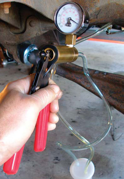
I used a vacuum pump to remove the old brake fluid without spilling any (Photo 20) and then flushed them with a 91-percent isopropyl alcohol solution. To eliminate all traces of alcohol, I blew out the lines with compressed air before installing new rubber brake hoses and reconnecting the metal brake lines at all four wheel cylinders.
Installing Shoes & Brake Hardware
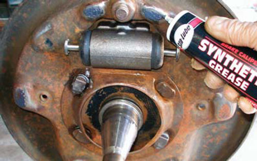
The next step is to place the new brake shoes and related hardware on all four brake backing plates, lightly greasing the three friction points where each shoe contacts the backing plate (Photo 21). Applied sparingly, a synthetic brake grease will allow the shoes to move freely and yet won’t melt and contaminate the brake linings.
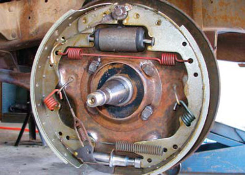
With my sketches and photos as a guide, I reassembled the new brake shoes with their related hardware— springs, cables and the like, which I’d cleaned in my solvent tank (Photo 22).
Because of Old Blue’s frayed and rusty cables, I haven’t trusted its parking brake for years. Given the scarcity and cost of replacement cables, I opted to remove the cables altogether.
Accordingly, with a rivet gun and pair of washers, I fashioned a weatherproof seal where the cables had entered the rear backing plates (Photo 23). When I’m ready to replace the cables, I’ll have only to drill out a pair of pop rivets.
It’s essential to avoid contaminating new brake linings with oil or grease. Therefore, before installing all four brake drums, I thoroughly cleaned their inner braking surfaces with wax and grease remover. Rubbing alcohol would probably work, too.
Bleeding the Brakes
With the drums installed, I set about filling the hydraulic brake system with fresh fluid and bleeding, or purging, the lines of air bubbles. I started by clamping the rebuilt master cylinder’s mounting flange— never the cylinder itself—in a vise. Then, using a large Phillips screwdriver that fit snugly in the back of the piston, I slowly depressed the piston about an inch and let it return just as slowly. I waited 15 seconds and then repeated the operation until I could no longer see air bubbles in the open fluid reservoir atop the master cylinder.
By tightening two bolts, I quickly reattached the purged master cylinder to the truck’s firewall and reconnected twin metal lines to its left side—one line for the rear brakes, the other for the front.
It’s possible to use a vacuum pump to draw through brake fluid and thereby charge the lines. I usually opt for the old-fashioned but equally reliable method of blocking the brake pedal down with a scrap piece of 2-by4 lumber. Pad your lower seat cushion with an old blanket and brace the 2-by4 against a piece of plywood, 2-by-6 or other larger chunk of wood to avoid damaging the seat cushion.
Start at the wheel cylinder farthest from the master cylinder—the right rear wheel—and work toward the master cylinder. Pump the brake pedal slowly several times, block it down and then open the bleeder screw on the back of the right rear wheel cylinder. You’ll have to pump, block and bleed several times.
Attach a piece of clear vinyl tubing between the bleeder valve and a pan on the ground so you can watch your progress. When no more air bubbles emerge from the right rear wheel cylinder, repeat the bleeding operation at the remaining three wheel cylinders in this order: left rear, right front and, finally, left front. Check and refill the master cylinder often as you bleed the brake lines and wheel cylinders.
Eager to learn whether the truck behaved any differently, I charged the system with regular DOT 3 brake fluid. Some experts say that the silicone brake fluid I’d been using tends to produce a spongy pedal.
But in my own little test I couldn’t detect any improvement in the truck’s braking performance after my switch back to the DOT 3 fluid.
Three Critical Adjustments
To wrap up the brake job, I needed to make three critical adjustments. The first and second adjustments involved the front and rear wheel bearings. The third adjustment was the brake-to drum clearance.
Each front drum uses two tapered roller bearings—an inner and an outer. I cleaned both bearings and their races in solvent and inspected all parts for wear. Finding everything bright and shiny, I repacked the bearings with synthetic wheel-bearing grease.
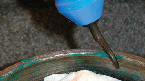
Wielding a seal driver, I tapped a grease seal into place on each front hub; these seals retain the inner wheel bearings behind them. One of the seals balked, I discovered, due to a burr in the seat. I ran a de-burring tool around the lip of this seat to clean it up and expand it slightly, after which the hub accepted the seal (Photo 24).
That done, I mounted the drums to the front spindles. At each front drum, I placed the outer wheel bearing over the axle spindle, followed by a heavy washer and an adjusting nut. Then I mounted the front wheels and tires and reached for my torque wrench.
At each side, I adjusted the front wheel bearings by spinning the wheel while tightening the adjusting nut to between 17 and 25 foot-pounds. This seats the bearings. Next, I placed a slotted sheet metal cover—a “nut lock”—over the nut while aligning the cover with a cotter pin hole drilled through the spindle.
Finally, I backed off the adjusting nut by two slots in the nut lock, installed a new cotter pin and snapped the dented old grease seal—the original metal “hub cap”—into place.
Because of rough handling before I bought the truck, my battered hub caps can no longer keep dirt and water out of the wheel bearings.
Therefore, I routinely smear a bead of clear silicone around its sealing flange before I install each hub cap.
Like cars and trucks decades older, my 1967 Ford front hubs contain a reservoir between the inner and outer bearings. This was originally filled with grease that would heat up and flow toward the wheel bearings. Because modern greases have more body, they will remain on the bearings, making it unnecessary to fill this reservoir.
Rear-Wheel Bearings Are Next
The wheel-bearing adjustment is much different at the rear axle, where it is necessary to adjust two large nuts on the end of the axle tube. Four steps are required for this bearing adjustment procedure: 1. Torque the bearing nut, the innermost of the two, to between 50 and 80 foot-pounds while turning the drum in both directions to seat the bearing. 2. Back off the nut somewhat. 3. Install a lock-tab washer and bend half of its lock tabs inward against the bearing nut. 4. Install and torque a lock nut to at least 100 foot-pounds and bend the lock-tab washer’s remaining tabs outward over the lock nut.
For step 2 in the preceding paragraph, the factory shop manual recommends backing off the adjusting nut by three eighths of a turn. This is an error, I assume, because it leaves the bearing with far too much end play. Instead, after tightening this hex (six-sided) nut, I routinely back it off one flat, or one-sixth of a turn.
Adjusting Shoe-to-Drum Clearance
With the wheel bearings now properly adjusted, the final step of the brake job is to set the proper brake shoe-to drum clearance. Do this from beneath the truck while it is still off the ground on jack stands and be sure to first install the wheels and draw the lug nuts up snugly. It’s hard to gauge brake drag without the inertia of a rim and tire to guide you.
Then, through an access hole on the lower edge of each brake backing plate, insert a screwdriver to turn a star-shaped adjusting washer positioned just inside the opening.
On Old Blue, pushing down on the star washer causes the brake shoes to expand; pushing up causes the shoes to contract. (These directions are reversed on a red 1967 Ford F-250 that I own, by all appearances a twin to Old Blue except it has a different brake set-up.)
A lock tab bears against the star wheel. You can adjust the shoes closer to the drum without the lock tab interfering. But if you want to back the shoes away from the drum, you’ll have to use a second screwdriver to hold the tab off the star wheel.
Set the wheel spinning and then push down on the star washer until the brake shoes just begin to scrape against the revolving drum. Repeat this procedure to get the same adjustment at all four wheels. Once you set the initial adjustment, there’s nothing more to do: a self adjuster inside each drum automatically maintains the shoe-to-drum clearance as the brake linings wear.
A Grabby Front Brake
My own brake shoe-adjusting session went well at three wheels. At the right front wheel, however, I pushed up against the star wheel as far as it would go—causing the shoes to contract or move away from the drum—and yet I could still hear the linings scraping against the drum. Furthermore, I could see through the access hole that, as the lining contacted the drum, the shoes seemed to grab at the drum, which caused the shoes to lurch in the direction of the drum’s rotation.
What’s up? I couldn’t figure it out. Ultimately, I removed the drum and returned the shoes to the brake shop. There, I learned that one of the relined shoes I’d placed at the right front wheel was bent. The heel and toe of this bent shoe, rather than its middle, was contacting the drum, causing the shoe to grab the drum and making it impossible to achieve the proper shoe-to-drum clearance. A replacement shoe cured the problem.
Fixing Brake Lights, Turn Signals
If it’s one thing to have good brakes, it’s quite another to alert other drivers to that fact. Unfortunately, not only my brake lights but my turn signals had quit working—possibly from the same cause?
After replacing the brake-light switch under the dashboard and fiddling with the fuses, I realized that I had a choice. I could either spend countless hours with my haphazard brand of electrical troubleshooting and maybe get lucky and solve the problem...or I could spend some money to get the trouble fixed right and right now.
As I was eager to get my truck back into service, I took Old Blue into a shop.
There, a mechanic determined that I had some poor contacts at my fuse box, a bad turn-signal switch and some deteriorating sucker connections—terminals that tap into other wires for power—from when I’d had some trailer wiring installed on the truck.
Several breaks in the insulation of my wiring harness had allowed wintertime salt to attack and rot the copper wiring within, I was told. A better way to make sucker connections, apparently, is to apply shrink-wrap to the wiring immediately afterward. The new turn-signal switch, pricey at $70, got my brake lights working again.
An Appetite for Rag Joints


I used the same shop to fix a chronic problem I’d been having with my steering gearbox connection. My Ford truck uses a fabric-and-rubber Thermoid coupling where the steering column bolts to the top of the gearbox. This so-called “rag joint” eliminates some road shock that would otherwise be transferred to the steering wheel.
For some reason—bent parts due to a broken cab mount, recently repaired?— I was tearing up a rag joint every two or three months. But no, upon inspection it didn’t appear that any parts were bent.
When I removed the latest rag joint and spun the steering wheel, the column’s center rod rotated smoothly, with no sign of wobble.
What was the problem, then? My mechanic fingered a bolt-down clamp on the column’s center rod just above the rag joint. It had slipped, he said, thereby allowing too much up-and down motion in the steering column’s center rod—and, consequently, the steering wheel attached to the rod’s upper end. In fact, a gap of a half-inch or more had opened between the top of the column and the steering wheel. I’d surmised (incorrectly, as it turns out) that my column-mounted turn-signal switch had somehow failed because of this undesirable gap.
Rather, the excessive up-and-down movement in the steering tube was rapidly ripping apart the rag joints. When the fabric and rubber failed, the metal collars above and below the rag joint began rubbing. I’d ground so much metal off the collar on the lower end of the steering column’s center rod that I replaced it with the center rod off a parts truck. At the shop, my mechanic placed the nice-looking center rod in the column, installed a new rag joint and adjusted the clamp to limit the rod’s up and-down movement. I’ve had no further problems.
In his final installment, Curt struggles to correct the engine’s low vacuum reading and performs a variety of other tasks to wrap up the mini-restoration of his old Ford pickup.


