INSTALLING A GPS SPEEDOMETER
The Project Vehicle’s Speedometer Needed Replacement and Aftermarket Parts Weren’t Working. So He Looked to the Sky and Satellites for an Answer.
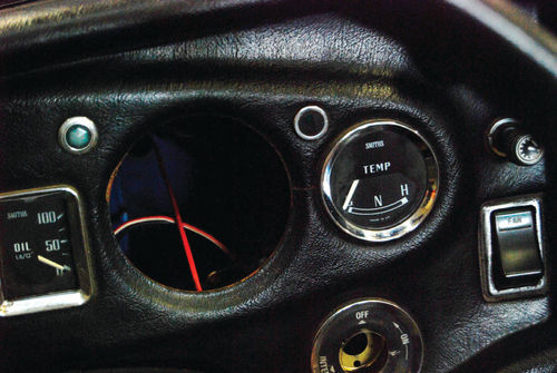
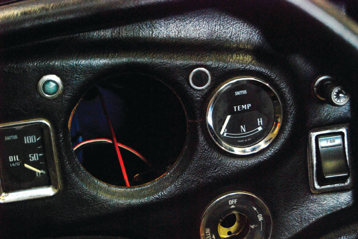
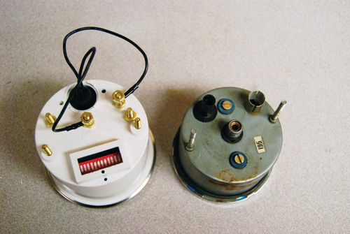
he speedometers in British sports cars are notorious for their inaccuracy. So it came as no surprise when we found that the speedometer in a ’76 MGB we were working on was bad and we set about trying to fix it.
Then we found that a parts catalog offered six different speedometer cables for this car. The one that’s correct depends on a combination of factors such as whether the car has a catalytic converter flag or if it has overdrive or if it has neither or both.
With all that in mind we ordered a new speedometer cable for the MGB…but it did not solve the problem. We had been told that reproduction cables don’t work well and also that the factory speedometers were pretty awful to begin with.
So instead of wasting time and money installing cables that might be correct or might work, we decided to look into using a GPS speedometer. (A GPS speedometer doesn’t require a transmission sensor and instead relies on constantly updated reports from Global Positioning System satellites to indicate a vehicle’s speed.)
Worth the Investment
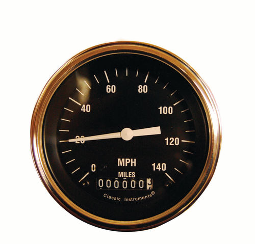
We knew that a GPS speedometer isn’t cheap, but neither is getting a speeding ticket—and sports cars are prone to getting speeding tickets. With this thought in mind, we called John McLeod at Classic Instruments (www.classicinstruments.com) in Boyne City, Michigan, and asked him about installing a GPS speedometer in the MGB.
We had attended a seminar that McLeod gave at a trade show and were impressed by how he ran his company. He was quick with answers to our questions and extremely helpful.
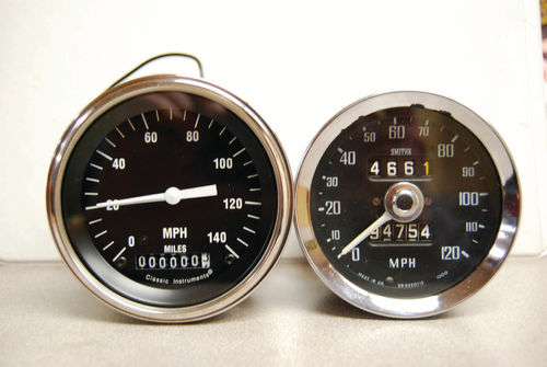
McLeod helped us pick out a style of speedometer that had the same basic look as the original MGB speedometer. He also emailed diagrams of three different-size speedometers available so we could measure and pick one that fit into the hole in the MGB instrument panel. However, we did have to open the hole up a bit with a rotary tool to get the unit to seat in the instrument panel.
The speedometer kit includes a bracket that holds the speedometer to the back of the dashboard. We were a bit worried that there wouldn’t be enough “meat” between the speedometer opening and other openings to give this bracket something to grab when the speedometer opening was enlarged. We measured carefully and squeezed the bracket tight around the speedometer housing and everything worked out fine.
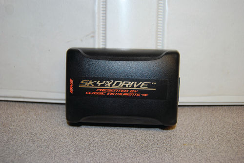
Electronic Sky Drive GPS Speedometer Sending Unit
To make the electronic speedometer operate correctly, we also needed a Classic Instruments Electronic Sky Drive GPS speedometer sending unit. This Sky Drive device eliminates the need for converters or pulse signal generators that need to be screwed onto the transmission. Such accessories can take up precious space and clutter up an otherwise neat setup. When you are using a Sky Drive GPS sending unit, you don’t have to worry about this. (Above we mentioned that this setup can be expensive. In our case, the speedometer was $265 and the Sky Drive was $250.)
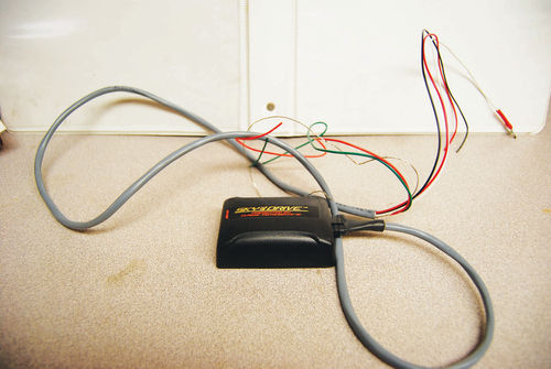
The best mounting location for the Sky Drive is anywhere inside the car where it will have a clear view of the sky. This guarantees a good satellite signal and troublefree speedometer operation. The Sky Drive can be easily installed. It has five clearly marked wires for a simple, straightforward installation. Making the wiring harness wires a bit longer allows for repositioning the Sky Drive in case it does not perform well and needs to be moved from the first chosen position.
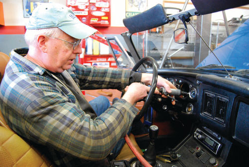
Once a good location is established, you can permanently mount the device and be confident you’ll be getting accurate, smooth readings. Bob Hansen of my shop, Gunner’s Great Garage, did the install on the MGB. He has the patience needed to disassemble a dashboard in order to get the original speedometer out.
As you take out other components, such as the heater, make sure you label the parts and keep them in a safe place. Many special fasteners are used on such components and aren’t easy to replace if you lose them. You should also have a manual (in our case the MGB Workshop Manual) to guide your disassembly.
Test Your Mounting Location First
In some cases, the Sky Drive will get adequate satellite reception even without a clear view of the sky. If you are planning to hide the Sky Drive somewhere that it isn’t in clear view of the sky, Classic Instruments recommends that you thoroughly test the Sky Drive in that location before permanently fixing it in place. The best way to determine if a mounting location works is to test it for a day. Make sure the speedometer operation is smooth, accurate and uninterrupted.
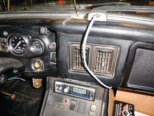
Once a suitable mounting location is determined, securely mount the Sky Drive using Velcro or double-sided tape. This will help prevent damage to the Sky Drive due to excessive jarring or vibration. In a tight car like the MGB there was no way to run the Sky Drive cable up through or behind the dashboard, but leaving it in plain sight is no worse than having a regular GPS plugged into a lighter outlet.
Status LED Is Helpful
The status LED is invaluable when setting up the Sky Drive. The status LED will light up red when the Sky Drive is powered, but has not acquired a satellite signal. The status LED will light up green when the Sky Drive is powered and has acquired a satellite signal.
Wiring Advice
The Sky Drive’s five wires include a red one for constant power (+12V to +24V), a black wire that is a chassis ground, a white wire that carries the speed signal to the gauge, an orange wire for speed independent output and a green wire for alternate power outputs.
Connect the +12VDC or +24VDC constant power source to the red wire in the Sky Drive harness. The Sky Drive requires between 1 and 4 minutes to acquire a good satellite signal after powering up. If a power source that has to be switched on is used, this initial signal acquisition will be required every time power is applied.
The Sky Drive draws very little power (approximately 60mA) and will not run your battery down under normal driving conditions. Power should be shut off, however, if the vehicle will be in storage for any length of time.
Connect the black wire of the Sky Drive harness to a good chassis ground point. Connect the white wire of the Sky Drive harness to the signal wire (or terminal) of your speedometer. Connect the bare wire (used for shielding of the Sky Drive harness) to a good chassis ground.
This GPS has an optional “overspeed” function: The orange wire of the Sky Drive harness is capable
of driving a load (like an indicator light) up to 1.5A at a user-set speed. The trigger speed for this output is programmed by running the calibration routine described below while the orange wire is tied to a constant power source. Be sure to disconnect the wire from the power source when the calibration is finished.
As an option, the green wire of the Sky Drive outputs +12VDC (up to 1.5A) when the vehicle is moving and stays on for five minutes after the vehicle is stationary. This is useful in situations where an ignition wire is difficult to locate or non-existent.
Calibration
When calibrating the Sky Drive, press the internal calibration button lightly using the supplied stylus to avoid damage. The calibration switch is delicate and if broken off will void the warranty. Use the stylus to avoid this. Ensure that the Sky Drive is connected to the speedometer, and that the speedometer and Sky Drive are powered.
Hold the Sky Drive in your hand. Locate the internal calibration button through a hole beside the harness opposite the LED. Gently press and hold the calibration button using the above-mentioned black calibration stylus. Continue holding the button until the speedometer pointer begins to rise (about 5 seconds). Continue holding the calibration button until the speedometer comes close to 50 mph (speedometers using miles) or 80 kph (speedometers using kilometers). Release the calibration button and begin “bumping” the button for fine adjustment.

If you pass the target speed, simply allow the pointer to return to zero and try again. There is no limit to the number of times the Sky Drive can be calibrated. Once the pointer reads as close as possible to 50 mph (80 kph), release the calibration button for five seconds. The pointer will return to zero. The Sky Drive has now been calibrated.
The Sky Drive calibration is retained even after a loss of power. There is no need to recalibrate the Sky Drive once it has been successfully calibrated.
Over-Speed Calibration Procedure
Repeat the standard calibration procedure while the over-speed warning output wire (orange) is tied to constant power. Instead of holding the calibration button until the speedometer pointer indicates 50 mph (80 kph), hold the calibration button until the speedometer pointer indicates your desired over-speed limit. Release the calibration button for 5 seconds and the pointer will return to zero. The Sky Drive’s over-speed limit has now been calibrated.
Remember to disconnect the overspeed output wire (orange) from the power source. You can now re-connect the output to your relay, lamp, etc.
Re-assemble the Dashboard
With the GPS-powered speedometer held firmly in place by the bracket mounted behind the dash and all the wires properly attached and the speedometer calibrated, you’re ready to start putting the dashboard back together. As we said, this takes patience. Once things are all buttoned up, clean up your tools and go for a ride.
Now you’ll know exactly how fast you’re going when you cruise past that squad car!


