
Install an Electronic Ignition
Most People Won’t Even Notice the Change Under Your Hood. But You’ll See Improved Economy & Reliability.
Editor’s note: Asour Long-time readers know, this publication was called Classic Auto Restorer until we shortened the name in January 1999 to better reflect our broad-based areas of coverage. We have a number of excellent articles archived from our CAR days and from time to time we’ll reprint one such as this how-to by Richard Prince, our Mechanic on Duty writer, that originally ran in March 1998. As an update, we searched the Internet for these types of electronic ignition conversion kits and found them listed for about $130. And one other thing, for readers who have just recently come on board, from July 1997 through February 2008 we printed in black-and white, which explains the noticeable shortage of color on these pages.
CHARLES F. KETTERING was, by all account, an engineering genius and many of the great advances in automotive technology originated in his Dayton Engineering Laboratories (later shortened to Delco). One such advance was the breaker point ignition system which Kettering developed in 1922. Prior to that, automobile engines relied on low-tension magnetos to ignite the fuel/air mixture.
Breaker points were light years ahead of the ancient magnetos, which dated back to the 1880s. The value of Kettering’s breaker point system is illustrated by the fact that it remained in use, virtually unchanged in design, for more than 50 years. Point sets could be manufactured very quickly and inexpensively, and they proved their reliability over trillions of miles traveled.
But while breaker points were state-of the-art technology for decades, innovation didn’t stop with Boss Kett’s ignition system. Engines, particularly those built after World War II, continued to benefit inside and out from better materials, assembly methods, machining capabilities and design breakthroughs. And as everything surrounding the contact points improved, the points increasingly became the weakest link in the chain.
Automobile manufacturers and supplier companies began looking at alternatives to conventional breaker points in the mid-1930s. By the late 1950s, racing and racing research had led to the first viable replacement systems. These early systems utilized electronic components in place of mechanical moving parts to overcome some of the inherent shortcomings in breaker point setups.
But it was not until the United States’ space program moved into high gear that the technology was introduced to manufacture inexpensive, reliable and highly effective electronic ignition system for the consumer market. By The Mid-1970s, most new cars were either equipped with an electronic ignition or were available with it as an extra cost option. Today, virtually every new car in the world is built with an electronic ignition.
The benefits of an electronic ignition system are pretty straightforward. Engines so equipped get better fuel economy, are more powerful and reliable, require less maintenance and emit a cleaner exhaust.
If you want to enjoy these benefits in your older car and are not committed to maintaining 100 percent originality at any cost, then an electronic ignition conversion is just the medicine the doctor ordered. And keep in mind that electronic ignitions have been improved over the years as well. What began under NASA’s space program has now been given a boost by the computer revolution. Today’s aftermarket electronic ignitions are inexpensive, reliable and easy to install. Not only that,they’re so miniaturized and discreet that it takes a very perceptive eye to spot them.
This article will take you through the step-by-step procedures necessary to install a Mallory “Unilite” electronic ignition conversion kit in an early 1960s Delco distributor. Mallory and most of the other major aftermarket ignition component manufacturers also market similar kits for almost any distributor used in the last 40 or 50 years.


Starting the Project
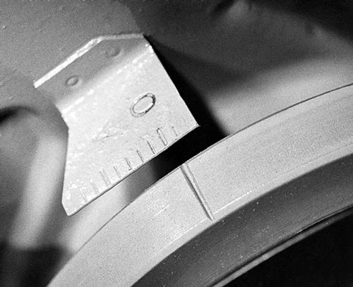
Begin by setting the engine so the number one piston is at top dead center on its firing stroke. This is a standard practice anytime an engine’s distributor is removed and makes it easier to reinstall the distributor in its correct orientation. An easy way to set the engine is to remove the number one spark plug and hold your finger over the hole while clicking the engine starter over and watching the timing marks which are on the harmonic balancer on most engines (Photo 1). Use a remote starter switch to click the engine over yourself or have a friend work the key while you do the rest. If you’re having a friend work the key, pull the high tension wire out of the coil so the engine doesn’t start while you’re setting the piston position.
The number one piston is at top dead center when the timing mark is at “zero,” and the piston is on its firing stroke when you feel compressed air coming out of the spark plug hole. If the timing mark comes around to zero and you feel suction from the plug hole, rotate the engine around once more to get the timing mark on zero again with compression coming out of the plug hole.
Number each spark plug wire to correspond with its cylinder and mark the corresponding towers of the distributor cap. I find it easiest to write the numbers on strips of masking tape and then wrap one strip around its respective wire and put another on the cap tower. Doing this will make it simple to install the wires in their correct locations later on. After the wires and cap are marked, remove and set them aside.
Disconnect the distributor wire from the ignition coil, remove the vacuum advance hose and tach drive cable, if your car is so equipped, unbolt the distributor hold-down clamp and remove the distributor. Make a mental note or, better still, a written note regarding the orientation of the vacuum advance canister and tach cable connection, if your car’s distributor is so equipped, so these parts wind up in the same orientation when you reinstall the distributor.
Inspection Time
After you remove the distributor from the engine, it’s a good idea to wash it with a mild solvent to remove oil, grease and any crud that has accumulated on it. Now is a good time to inspect the distributor to see if there is anything wrong. Check the main shaft for wobble by grasping the housing in one hand and trying to move first the top and then the bottom of the main shaft in its bore. The shaft should be snug and if there is more than slight wobble at the top or bottom you should replace the bushings and inspect the mainshaft for wear or score marks where it rides in the bushings.
While the distributor is out you also should take a look at the gear that drives it and at the tang at the bottom that drives the oil pump on most engines. If either of these parts is damaged, it should be replaced.
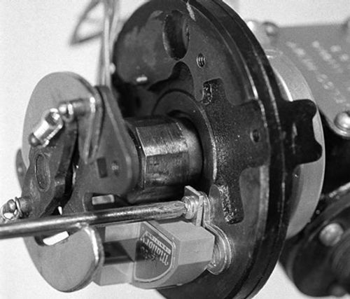
After the distributor has been cleaned, inspected for wear or damage and given a clean bill of health, it is time to install the conversion kit. Remove the ignition rotor, contact points, condenser, point trigger wire and point trigger wire grommet (Photo 2). The only part from this group you need to reuse (assuming it is in good condition) is the ignition rotor.
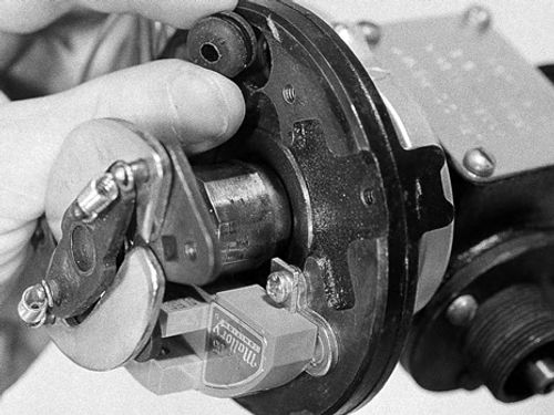

Install the electronic ignition module mounting plate flat against the breaker plate where the breaker points and condenser used to be located. Two 8-32 x 1/4-inch flathead screws are included in the kit to mount this plate (Photo 3).
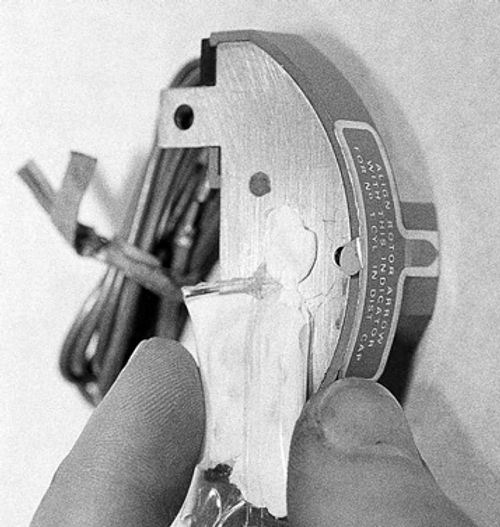
Next, apply a thin coat of the special white silicone grease that’s supplied to the bottom of the module. This grease acts as an insulator and helps to prevent the transfer of heat to the module. Excess heat can eventually damage the module, so don’t forget this step (Photo 4).
Use the two 6-32 x 3/16-inch screws included to mount the module to the mounting plate that you’ve already installed on the distributor’s breaker plate (Photo 5). Install the new rubber grommet supplied in place of the old point trigger wire grommet that you previously removed (Photo 6).
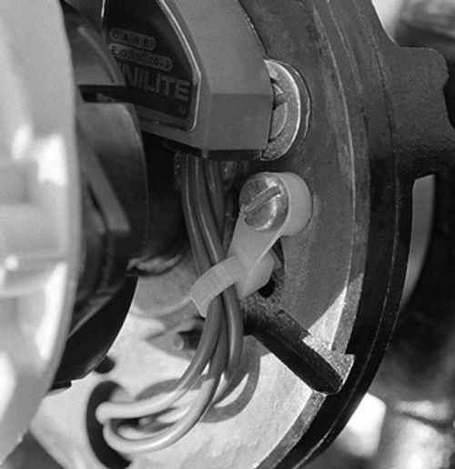
Pass The three wires coming out of the module through the grommet and then secure the three wires with the special wire tie in the kit. This wire tie goes around the wires like an ordinary wire tie but it also has a tab with a loop on its end. The tab with the loop permits you to screw the tie-down to the distributor so the wires are held securely and away from the rotating parts (Photo 7).
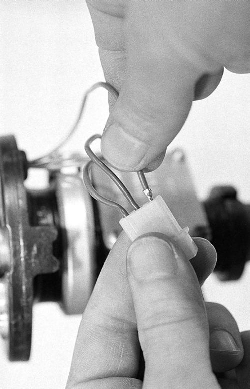
Snap each of the three module wires into the plastic female connector in the kit. The plastic connector has tiny numbers molded in it to designate each of the three receptacles. Slide the green wire into number one, the brown wire into number two and the red wire into number three (Photo 8).
Install the two-piece plastic shutter underneath the plate where the ignition rotor mounts. (It’s called a “rotor drive plate.”) Two 8-32 hex head bolts come up through the holes in the two-piece shutter, pass through the holes in the rotor drive plate the ignition rotor screws previously threaded into, and pass up through the rotor itself (Photo 9). Two nuts then thread down onto the hex head bolts and secure both the shutter and rotor to the rotor drive plate (Photo 10).
Put It Back
The distributor now can be reinstalled into the car. Squirt some oil into the distributor housing just in case the oil was washed out when you cleaned the unit, make sure the gasket is present, and drop the distributor into the engine. Before dropping it all the way, make certain the vacuum advance and tach cable connections are positioned correctly. To get it to insert all the way, you may have to jiggle the distributor a little bit to get its lower gear to mesh properly with the drive gear inside the engine.
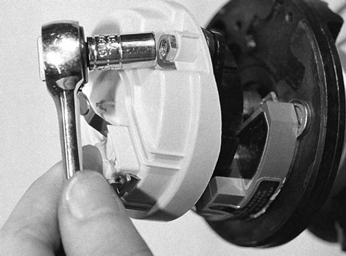


The kit comes with a relatively short, three-wire harness that needs to be installed into the car. Connect the brown wire to a good, secure ground—this wire comes with a large hoop soldered onto its end for that purpose. A valve cover bolt or one of the bolts holding the ignition coil bracket are usually convenient places to ground it (Photo 11).
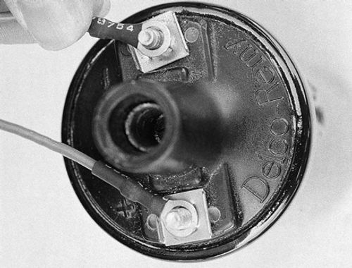
The other two wires also come with hoops soldered on and they both connect to the ignition coil. The red wire goes to the positive terminal (along with the car’s existing “hot” lead that was previously connected to this terminal) and the green wire goes to the negative terminal (Photo 12).
The harness you just connected has a plastic male connector on its end that plugs into the female connector coming out of the distributor (Photo 13). Before plugging the connectors together (they are keyed and can only go together one way), make sure the wire colors will line up when they are joined and double check each of the wire connections you made. If you accidentally cross any of the wires you will fry the module and have to buy a new one, so don’t make any careless mistakes. After you have double-checked everything, plug the two connectors together.
Install the distributor cap and spark plug wires in their correct locations, fire up the engine and set the ignition timing. Setting the timing is necessary because the distributor was out of the engine and even though you put it back in the right spot, it isn’t likely to be exactly where it should be. After the timing is set, you have completed the entire installation. The only thing left to do now is go for a cruise and enjoy your handiwork.
Resource
Mallory Ignition
10601 MemphisAve. #12
Cleveland, OH 44144
Now observing its 85th year.


