
How -to When That Lever Snaps…
His Heating & Air conditioning system Just Wasn’t Delivering. The Culprit: a Broken Control, Now Repaired.
IN THE EARLY days, vehicles didn’t have heaters. Later on heaters showed up as an option (if you were lucky). As time passed they became standard equipment, and air conditioning started to appear. Soon we came to expect these creature comforts, and there was no going back. In fact, it’s come to a point where a problem with our vintage vehicle’s climate control system greatly reduces our driving pleasure, at the very least, and in some cases may make a session behind the wheel of our favorite car or truck almost impossible.
Now, if you happen to be one of our readers that owns and drives an early, “non-heated” vehicle, more power to you! For everyone else, the experience I had with my vehicle may be worth noting.
The problem I encountered was low airflow from the vents with the A/C on— even though the fan was working properly. The discharged air was cold; there just wasn’t enough of it.
In this case the vehicle is a 1987 El Camino although the same situation could occur with other vehicles as well. GM is known for using components for decades, and it’s likely the same (or a very similar) air delivery system was in use over a long period. Even if your vehicle is not a GM product, you might find the following repair information helpful should you encounter a similar problem.
Finding the Problem
When I first experienced the low air movement, my initial thought was there must be a vacuum leak. After all, unless something had been serviced, all the rubber components in the system were more than 20 years old. That includes parts of the control panel, hoses and the vacuum actuators. Another thought was that something had broken off within the air delivery module and had wedged a vent door, not allowing it to fully open or close.
A visual inspection seemed like the best approach, but where should I start? I could remove the climate control panel and inspect it and the connections, or look at the air delivery module to inspect any cables and vacuum diaphragms. I decided to start the visual inspection with the module, simply because removing the glove compartment was easy, and it would give a good view of it. In other words, it was the “path of least resistance.”
The module I’m referring to is the unit that holds the fan, heater core and A/C Evaporator. Obviously if your vehicle has heat only, there will be no A/C Evaporator. The module directs air to pass through the heater core, A/C Evaporator, or delivers fresh outside air. Often it will create a mixture of these depending on what is called for. It also will deliver air where you want it, either to the floor; mid-level vents; or up to the windshield for defrost or defog mode. All of this is accomplished by opening or closing specific doors within the module.
In some instances removing the glove compartment may not be necessary, but usually it makes it easier. On the El Camino, this step is simple and straightforward. Removing several screws at the hinge and one from the cable that limits its opening is all that’s required. The glove compartment and the door are all one piece, and now can be lifted out. Many vehicles will require door removal followed by taking out several additional screws that retain the cardboard or plastic “box” itself.

Some compartments will have a light which may or may not need to be removed. The light will often be a push-in fit and sometimes is incorporated with the switch, typically with one wire attached to it.
Once the glove compartment is out of the way, you have a window through which to look at the module.
Working the control levers and watching for activity at the module was the first test. To verify the operation of vacuum-driven components you will need to secure the vehicle, and then start the engine.
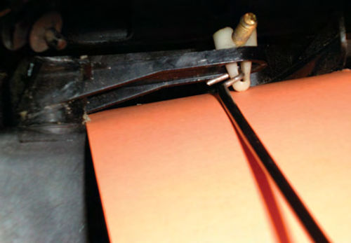
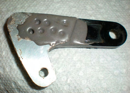
Well, I was in luck! While moving the “Cold—Hot” temperature lever, I noticed cable movement with no function. Photo 1 shows the broken plastic door lever I discovered. The red arrow indicates the break. Just above it, still attached to the temperature cable, was the piece that had broken off. To verify that this was the only problem, I worked the door lever by hand with the A/C on. While pushing the lever all the way forward, full air discharge from the vents returned.
A Look at the Temperature Lever Functions
For background purposes, let’s review the temperature lever positions.
Full Cold: All air to pass through the A/C Evaporator (or venting in outside air for non-A/C equipped vehicles). The heater control valve receives a vacuum signal from the control panel and remains closed, not allowing coolant to enter the heater core.
Full Hot: All air passes through the heater core, and the absence of a vacuum signal opens the heater control valve thus allowing coolant to flow through the heater core.
Anywhere In Between: This positions the temperature door to allow air flow from both sources, yielding a mixture. The heater control valve receives no vacuum signal and would once again be open.
These functions hold true for my El Camino and probably most other GM vehicles of the day. Note, however, that not all vehicles have a heater control valve. Furthermore, another manufacturer’s heater control valve might function just the opposite, opening when a vacuum signal is present. Refer to your shop manual to verify these facts.
Back to the Broken Lever
You can see in the photo that the lever’s location is very close to the underside of the dash; there is probably less than one inch of clearance. My first thought was that removal of the module itself would be required to gain access to replace this part. Decisions had to be made on the approach I would take, but in the meantime the vehicle was still needed for daily use. So as an interim fix, I used a thin piece of gas welding rod and connected it to the adjusting nut on the end of the lever as you see in Photo 2. This simply hooked through the slot in the nut, and as long as it was handled gently, would work fine as a temporary means of temperature control. As an extra measure of safety, I had a piece of very thin tubing that I slid over the wire to avoid any possibility of conductivity. This should never be an issue, butI was just playing it safe. Due to the way the glove box swings out when the door opens, I was able to have this wire rest inside the glove box so it could be reached fairly easily to adjust the temperature. Keep in mind that even though the cable is not connected, the control panel lever must be moved off cold to signal the heater control valve when heat is desired,so you will have a second step here. Remember this was just a temporary fix, not something I would be boasting to my friends about.
Remove It, Or Do An On-The-Car Repair?
I don’t know if a new replacement part is available from GM, but I decided that a sturdy, dependable repair could be made. Initially I was going to make the repair with the lever still in place, figuring that it would not be easily removed. Unfortunately, details like this are sometimes overlooked in the shop manual, assuming (I guess) that you already know.
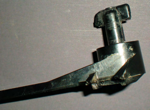
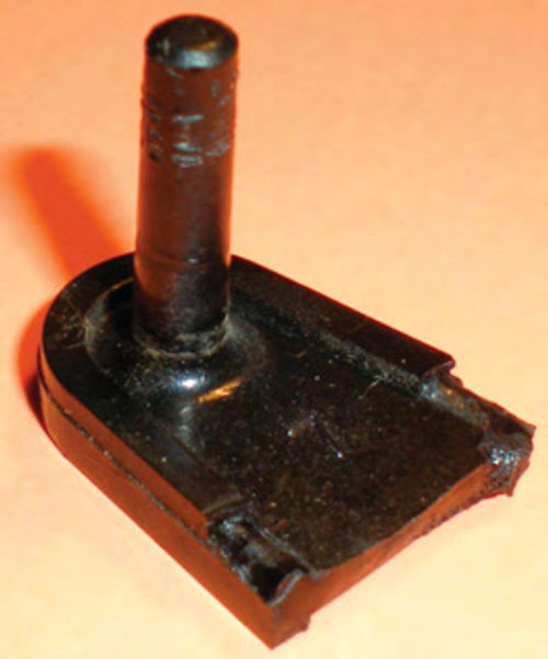
After giving it some thought, and realizing that this lever didn’t have any other hidden or mysterious functions, I figured it should be removable without too much of a fight. Using a mirror to view down from the top I looked for a screw or some other means of attachment, but there was none. Maybe it simply “popped” in and out? The first step was to disconnect the temperature door rod from the lever. This was accomplished by squeezing the bottom of the white adjustment nut (visible in Photo 2 where the wire is going through it) and then pushing it up and out. Once disconnected, I tried prying gently upward on the lever without success. The next approach was to continually pull up on the lever while rotating it. That was the combination. At a certain point it lifted completely out. Photo #3 shows the “T-type” end that had to be lined up for removal. In actuality gravity keeps this lever in place while in the vehicle. This “T” keeps the part from simply falling out if the module were to be removed.
Deciding How To Repair the Part
The first thought might be to simply epoxy the broken piece back on, but it would probably last just long enough to get everything back together and once again fail. Instead I decided to copy the shape of the broken bellcrank and duplicate it out of aluminum. I chose aluminum because it is a soft material that’s easy to work with, strong…and I had some on hand. It’s available most anywhere.
The piece of aluminum would be bonded directly on top of the existing part using JB Weld epoxy. You might think I am contradicting what I said earlier with regard to the strength of an epoxy repair, but it all has to do with the way things are attached. With this repair the new aluminum part will have a very large surface area to bond with. If I had simply tried to epoxy the broken piece back on, it wouldn’t have much at all.
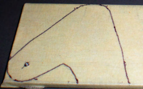
The broken pieces seen in Photos 3 and 4 were temporarily reunited, and its outline was then traced onto a piece of 1/8” x 1 1 ⁄2” aluminum flatstock. Photo 5 shows the results. Notice in the lower left corner that it has been center punched. This will be drilled and tapped later for the location of the pin. It’s much easier to perform any drilling first, and then cut the piece from the stock. Also, remember which side is “up.” If you forget you could end up creating a mirror image of the part you need.
What If the Part Had Not Been Easily Removable?
If we hadn’t been able to remove the part, we would have needed to obtain some measurements. Odd shapes make this difficult. One approach is to use plumbers putty to create an impression of the old part. Another is to use “layout dye” to coat the edge of the old part and then quickly press a piece of paper against it to create a transfer. Layout dye is a liquid used by machinists to allow scribing patterns onto “stock” once dry.
However, these methods may not work well in a tight area. Putty could be difficult to remove without accidentally stretching and distorting it, and a dye transfer could easily be smudged. Consider using a small piece of carbon paper to create a transfer. (You remember carbon paper; it’s the blue stuff that used to be placed between pages to create a copy when typing.) Rub it on the perimeter edge and it will leave a small amount of dry carbon. Laying a piece of paper over it and rubbing will create a transfer. These are a few methods, and you may have your own thoughts as well.
Let’s Start Building
Before drilling, I need to know what would be used for the pin. The original plastic one was slightly tapered and measured .155” in diameter,so 5/32” (.1562”) steel drill rod would be perfect. Unfortunately,all I could locate was 3/16” (.1875”). Discovering a length of 3/16” brass rod in my shed, it became the material of choice.
Next was to determine the length needed for the new pin, keeping in mind the piece of aluminum will be sitting on top of the existing part. Additional length will be needed for it to thread into the aluminum stock. A total length of 1 1 ⁄4” was decided on. This could have been a bit long, but it’s easy enough to trim later if necessary.
I am fortunate enough to have a lathe,so the brass rod’s diameter was turned down to the desired .155”. Finally, the opposite end was threaded using a 12-24 thread die. Photo 6 shows the newly created pin with the cable retaining ring on the end.
No Lathe? There Are Options
1. The new pin could have remained its full 3/16” diameter, and the opening in the metal clip that slides over it would need to be enlarged by 1/32” (.0312”), followed by a new means of securing it, such as threading the opposite end and using a nut.
2. If you are like me and prefer not to do that, or it simply isn’t an option because the cable itself is what slides over the pin, consider using a battery powered drill to hold and spin the short piece of brass rod.
With the aid of a belt sander or bench grinder, run the drill in the opposite direction against it. Brass is a soft material, and will remove quickly. Check its diameter frequently so as not to remove too much stock. Once it’s where you want it, remove it from the drill and thread its end. This method may sound a bit primitive, but it will actually do a decent job. Remember to wear eye protection during this procedure, and if a bench grinder is used, dress the grinding wheel when finished because the soft brass will load up the wheel.
Now it’s time to drill and tap the location on the piece of aluminum. For a 12- 24 tap, a #16 (.177”) drill bit is required for the initial hole.
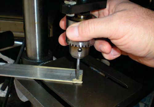
A good method to square up and start a tap is to use a drill press as seen in Photo 7. Note that nothing in this step is being performed under power. Simply snug the tap in the chuck; then raise the table until the tap is positioned in the hole; now rotate the chuck by hand until the tap is firmly started. Once established, loosen the chuck and release the tap while it’s still engaged with the aluminum stock.
Now free of the drill press, continue the tapping operation following the normal procedure of threading forward a bit, then reversing the direction slightly to break off the “chip.” Don’t forget to use oil. There are special lubricants for thread cutting, but if you don’t have any on hand, use what you do have. To increase the bond between the pieces, I drilled several small holes in the aluminum. A hacksaw was then used to cut out the new part, followed by a file to smooth off the edges. No, this doesn’t have to be exact, but a close match makes it easier to line up and maintain the correct geometry with the existing part.
Before you start mixing any epoxy, check the fit of the new piece, and scuff up both mating surfaces with a file or sandpaper to increase the bond. Once satisfied, mix up a good two-part epoxy and apply it to both surfaces, then sandwich together. My preference is JB Weld. Why? Because it has always performed well for me over the years, it’s very strong, and I like its slow setting characteristic.
Make sure all is lined up properly, and remove any excess epoxy that’s hanging over the edges. Squirts of epoxy oozed up through the holes that were drilled in the aluminum. This was leveled out, leaving the excess for added strength. Photo 8 shows the repair once it was completely cured. Most epoxy will set in about five minutes; JB Weld takes closer to an hour (jbweld.net). Regardless, check on the repair frequently because it may try to move.
You may be wondering why the aluminum repair piece doesn’t cover the entire top of the old lever. It easily could have, and might look a bit more appealing. There were several reasons:
1. It would raise the location where the door rod adjusting nut would sit. Not really an issue here, but in some cases it might be. Then, enlarging the hole in the plastic lever would be required so that it would snap properly into the aluminum, and allow the room needed for removal.
2. From the standpoint of strength, it wasn’t necessary.
3. Simplicity!
4. This was the size material I had on hand in my shed.
And to those who might be asking, “why not just remake the entire piece”?
1. This isn’t a skills competition. The idea was to keep the repair simple, and hold the number of necessary project tools to a minimum.
2. Unless Required from a visual standpoint, it certainly wasn’t needed when considering the stress applied to the part.

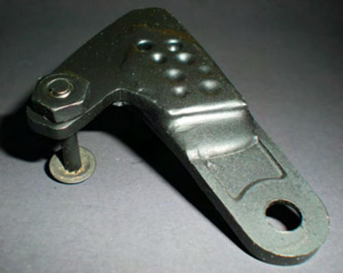
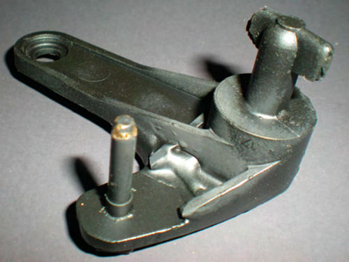
Photos 9 and 10 show the finished part with the pin in place, and a quick coat of flat black paint. A jam nut was used on top of the aluminum to lock the pin in place. I hadn’t planned to do it this way, but it made good use of the extra threads that were protruding through the top. The original plan was to secure the threads by either applying Loctite or some epoxy. The part was then replaced and both the cable and temperature door rod were reconnected. Photo 11 shows it in position and ready for use.
Next, using the control lever, make sure that the dooristraveling fully in both directions.Listen for a “thud;” this indicates it’s properly positioned. On many vehicles the position the cable is clamped in controls the adjustment, but not on this El Camino. Had adjustment been required, it’s accomplished by squeezing the bottom of the white nut allowing it to be removed. The manual indicates an initial adjustment of 1/4” of the threaded rod exposed, facing toward you. All that remains is to replace the glove compartment in reverse order, and the job is finished.
Some Other Approaches
If you have a similar heating or A/C problem but it’s not quite as obvious as mine was, check the following:
1. Verify that all the doors are opening and closing fully within the module. Listen for a “thud” or “clunk.”
2. Is any binding felt when the controls are operated? If there is, verify that nothing external is interfering with the operation. A problem could also exist within the module. It could be a broken part, or even an accumulation of debris inside it. Unfortunately, this will require getting inside of it, which usually means removal of the module.
3. Is there a broken cable? If you discover that a control cable’s coiled end has broken off, consider repairing it. KD tools #495 cable coiling pliers were designed specifically for that purpose.
4. Check for restricted air flow. On vehicles like this El Camino, an air intake screen is located below the passenger wiper blade, where leaves and debris can accumulate if neglected. This can result in reduced air flow through the module.
5. No heat: This may be due to a malfunctioning heater control valve, or an internally restricted heater core.
There are a number of things to look for and be aware of when dealing with these A/C and heater problems.Consider fabricating simple parts if they are needed, and remember that in many instances a repaired part can be strong, reliable and almost undetectable.
Tools Used In Making This Repair
1. Basic hand tools—1/4” socket set; needle-nose pliers; screwdrivers for glove box and cable removal.
2. Drill press—for drilling and for starting the tap.
3. 12-24 Tap & die—for threading the pin and aluminum stock
4. Hacksaw and file—for cutting out the piece and smoothing its edges.
5. Lathe—used to turn down the diameter of the pin. (Note: See lathe alternatives mentioned in the text.)
6. Bench vise—to hold components during cutting and threading.


