
How -to Balancing Brake Rotors
A Number of Conditions Can Cause Annoying Vibrations. This Approach to Rotors Can Solve One Problem.
ViBRATIONS WHILE DRIVING your vehicle are aggravating, and take a lot of the enjoyment out of an afternoon cruise. There are a number of things that can cause them, and tire balance is probably the first thing that comes to mind, but you need to broaden your thoughts to rotating mass in general.
Drive train issues can certainly create vehicle vibrations. This can be due to a driveshaft that’s damaged, out of balance, or has worn components such as universal joints. The same would apply to front wheel drive vehicles with regard to their CV joints.
A badly worn transmission tail housing bushing and even the pilot bushing for a manual transmission input shaft are possibilities. I had an annoying vibration in my 1966 Malibu, and discovered it was the pilot bushing. The vibration would usually disappear if the clutch pedal was pressed and released again during travel.
This allowed the transmission input shaft to reposition itself and often correct the problem. Anywhere there is rapidly rotating mass in the vehicle there’s the potential for vibration, and if it’s supported by bushings instead of bearings, pay close attention.
Check the Tires and Wheels
Before you start chasing vibration problems make sure that the vehicle’s front end, tires, wheels, and brake rotors/drums are all in good shape. A distorted rim or a tire with a tread separation will never perform as it should, and can be dangerous.
Tires and wheels have maximum runout specifications that should be checked. A general rule is a maximum of .060” radial and lateral runout, but if your service manual says otherwise, go with that.
A quick check can be performed by first driving a few miles to round out the tires, then using something as simple as a cinder block up next to the elevated tire to view the runout. Allow the high spot of the tire’s tread to just make contact with the cinder block, and when the largest air gap is noticed, you can use drill bits to judge the distance between the tire and cinder block. If .060” is the tolerance you are working with, a 1/16” (.0625) drill bit is close enough to be considered the maximum. The same test is then performed on the sidewall of the tire, however if there are raised letters this will make the task more challenging.
Photo 1 shows a gauge made specifically for this purpose, but as noted, the cinder block and a set of drill bits will do the job.
Some situations may require dismounting the tire from the rim to check and verify the rim’s runout. The rim would be mounted back on the vehicle and checked in the same manner as thetire. This will determine if the problem is with the tire, rim or possibly both. Also, reorienting the tire to a different position on the rim can often bring the assembly within specifications.
Excessive runout will make a tire bounce as you pick up speed and will create a vibration.
Consider Brake Drums and Rotors
Brake drums and rotors can also be out of balance, and this is not uncommon. Back in the October 2005 issue of Auto Restorer I wrote an article on balancing brake drums using a tire bubble balancer, but with the passage of time I realized that front brake rotors need to be included in the topic, although the procedure is a little different.
Tires and rims can be computer balanced all day long, but if either brake drums or rotors are out of balance, a vibration will remain. Yes, a Hunter or Stewart Warner spin type balancer can be used to spin balance the wheels on the vehicle. This method will balance the entire assembly, and in my opinion is still the best. Unfortunately, when the tires are rotated, this balancing process will have to be repeated. Even if this method of balancing is chosen, it’s best to have “components” balanced as well as possible, requiring less weight compensation on the rim in the end.
Rotor Inspection
Before investing time into checking and correcting brake rotor balance (or drums for that matter), perform any brake maintenance that might require resurfacing of the rotors. If none is necessary, make sure the rotors are within specifications. Most rotors are stamped with a minimum thickness on the face of the hub, otherwise this information can be found in your service manual or Chilton. If they are under size (having been worn too thin), find replacements. If deep scoring is visible on the rotors’ surface, it may require replacement or machining, and having the brake system serviced.
Don’t be misled by the “tracking groove” that GM machined into the center of many brake rotors—that was purposely designed in.
If there is a pulsation in the pedal when applying the brakes, you may have a rotor that has thickness variations or too much runout (warped). This won’t have an effect on the rotor’s balance, but if resurfacing is required to correct it, that will affect it.
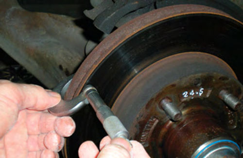
A micrometer can be used to check for thickness variation as well as minimum thickness. In Photo 2, I am doing just that. Also note the stamping on the hub of the rotor which has been highlighted in white. On this rotor specifications are given for the minimum thickness in millimeters. If you are using tools calibrated in inches, take the millimeter specification for the rotor and divide it by 25.4, this will give you the measurement in inches. For example, this rotor is marked 24.5(mm) minimum thickness; 24.5 ÷ 25.4 =.965”.
Allowable thickness variation for most rotors is usually .0005 or less. Considering that a human hair measures .003, that’s not much.
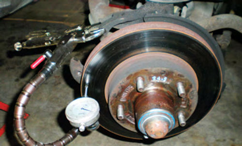
A clamp-on mounted dial indicator does an excellent job of checking rotor runout as seen in Photo 3. These specifications will need to be looked up in your shop manual. If there is adequate stock remaining on the rotor, most abnormalities can be corrected by having them turned and trued on a brake lathe at the local machine shop. This rotor is starting to get thin, but is still OK.
Getting Started
The subject for this article is my 1987 El Camino. It’s equipped with one piece, 10.5”ventilated brake rotors.The venting area between the inner and outer friction surfaces is where weight will be placed to correct any imbalance. The balancing operation will be performed with the aid of gravity and a relatively inexpensive motorcycle tire balancer that was purchased from Harbor Freight Tools. While I’m not a huge fan of Harbor Freight, they occasionally offer something that can be very useful.
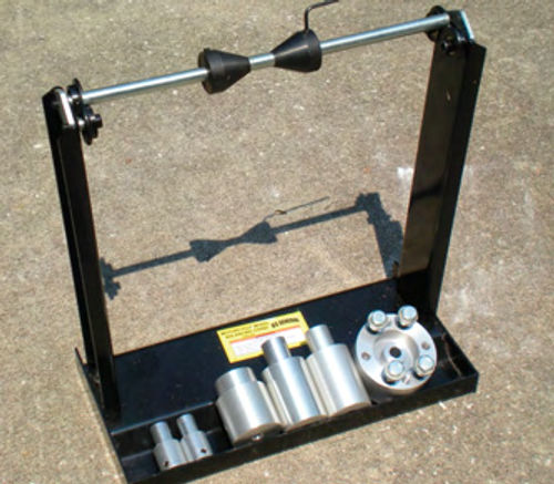
Photo 4 shows the balancer (item #98488), and it includes two tapered cone-type collars that you see on the arbor. As of this writing it’s priced at about $50.
In the base tray of the balancer are several other adapters that might prove to be useful. These are sold separately. Also, making adapters is an option if you have a lathe, or know someone who does. Don’t forget to check with any local technical schools. If you can supply the specifications desired, a student will be assigned the project, and the cost is usually based on the material used.
This tool works well for the task of balancing hub-mounted rotors or even brake drums that can’t fit onto a bubble tire balancer. This would include most hub-mounted drums as well as the splined type.

(Some readers might notice a slight resemblance between this unit and a tire balancer that Snap-On made about 50 years ago, though there is no mistaking the difference in quality.)
To get started, pick a side and remove the brake rotor as though you were preparing to do a brake job. Remember to use the usual safety precautions such as proper placement of jack stands to support the vehicle once it’s lifted. Secure the caliper so that it’s not suspended with the brake hose supporting its weight. Remove the bearings, hub seal and any excess grease from the center of the hub. If there is any loose flaking rust, scrape or wire brush it off, but use caution to keep any from entering into the hub. A wire wheel on an electric drill is also a good approach.
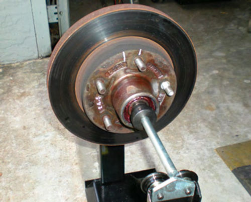
With the balancer placed on a relatively level surface, remove the arbor and slide it through the rotor’s hub, approximately centering the rotor on the arbor, and then fit the cone adaptors snugly up against each bearing race. If the races are too large and the cones pass through them, reinsert the wheel bearings, center the cones in the bearings and snug down the set screws as seen in Photo 5. This is where extra adapters may be handy to fit certain rotors. This may be splitting hairs but positioning the cone set screws so they are 180° apart eliminates any question with regard to maintaining balance (just as you would when replacing a drive shaft’s universal joints with regard to grease fittings).
Several Methods for Identifying a Heavy Spot
If the rotor immediately starts to roll when the arbor is positioned on the balancer uprights, there definitely is a heavy spot. Heavy spots should fall to 6 o’clock, or very close to it. Spin the rotor several times and observe it. If it comes to a gradual stop, and its at-rest location ends up different each time, the rotor’s balance is good. If, on the other hand, it seems to continue rolling past where it should have run out of inertia, or even changes direction and begins rolling backward before it stops, you have a heavy spot. Note, however, a very slight backward roll at the end of forward rotation may very well be acceptable. You will quickly begin to recognize what is and isn’t acceptable, and these funny movements will be easy to spot.
Mark the rotor at 12 o’clock; this should be the light spot. Rotate this spot to different locations like 3 and 9 o’clock; does it roll back to the 12 o’clock location? Even spin the rotor again and see where it ends up. It may not end up at exactly the same location each time, so multiple tests will fine-tune the location. Make additional marks for any new spots that stop at 12 o’clock. They should all be close together. Take the two marks that are farthest apart and make the final location halfway between the two.
Note:It is possible to get a false reading if the heavy spotstops exactly at 12 o’clock. The reference marks would now be around 6 o’clock, almost 180°off.If That’s the case, simply disregard this reading.
Ultimately the concern is the lightspot, where weight will need to be added.The two white lines visible at 12 o’clock on the rotor’s hub in Photo 5 indicate the light spot.
What If Balancing Weights Are Already In the Rotor?
It’s not unusual to find balancing weights located in the ventilated area of the rotor. One was discovered in this rotor, and is highlighted with white paint to make it easier to spot in Photo 6. The weight is inserted from the outside edge of the rotor, and its ends are spread apart like a cotter pin, so it’s snug, and won’t come flying out. Don’t be afraid to remove it and recheck the rotor balance; but first mark its location. Sometimes replacing the weight in a different location can correct the balance. A big plus to finding one of these weights is that it can be used as a guide to make others.
To remove this weight, first take the rotor and arbor assembly off the balancer. Rest the rotor on the floor or a workbench in the vertical position, locate the weight so that it’s facing skyward as is seen in photo 6. Next insert a long 1/4” drift pin in the vent hole on either side of the balancing weight, and tap it with a hammer. This will partially straighten one of the bent-over legs. Now repeat this procedure in the hole on the other side of the weight. Note that the arbor can remain positioned through the rotor during this procedure, but don’t perform this operation with the arbor resting on the balancer’s uprights; you could bend the arbor, or damage the balancer’s bearings.
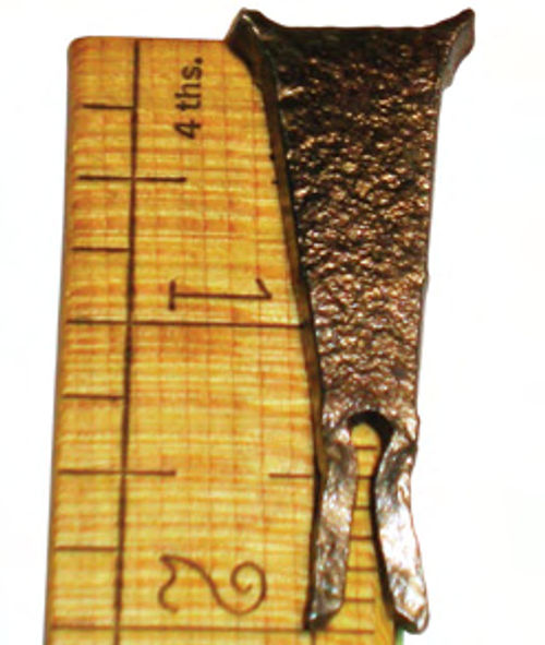
Now position the rotor so you have a good view and access to the bottom legs of the weight. Needle nose pliers didn’t have enough leverage to squeeze the legs together, so I used a needle nose Vise-Grip. Once the legs are adequately straightened, a light tap with a hammer will knock the weight free. Photo 7 shows the weight removed from the rotor. This wedge-shaped weight is 3/16” thick; 2” in total length; the legs start to separate at 1 3 ⁄8” down from the top; are 13/16” at the widest point; and 5/16” wide where the legs take form.
Let’s Determine and Make the Weight That’s Needed
The rotor was again checked with the weight removed, but it was still out of balance. Placing the weight into different vent holes between its original location and the light spot we had first marked improved it, but more weight was needed.
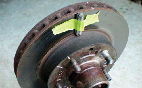
If you have access to some old tire wheel weights, they are an excellent aid for determining how much weight is needed. Clean the friction surfaces of the rotor, and using masking tape position a tire wheel weight where it’s believed to be needed on the rotor as seen in Photo 8. There is a lot of fine-tuning in locating the position and correct amount of weight. I started with 1 ounce, then went to 1 1 ⁄4 ounce, and finally settled on 1 ounce. When the rotor can be stopped at any position on the balancer, and doesn’t start to roll, you won’t get it any better.
So, the next job is to duplicate the amount of weight needed (1 ounce) in a wedge shape like the one that was removed. Using an old postal scale, the steel wedge was checked and found to be just over 1/2-ounce. Next, the wheel weight was placed on the scale. While it was marked 1 ounce, it actually was slightly less.If all the measurements were the same, doubling the thickness of the wedge to 3/8” should also be close to doubling the weight, thus slightly over 1 ounce. Its weight could then be reduced by grinding if needed. I mention that because once the weight is made and placed in the vent hole, it won’t be exactly the same as what was taped on the surface.
For example, a wedge-shaped weight will have most of its weight at the large end, closest to the outer edge of the rotor. The tire wheel weight that was used for gauging was fairly evenly spread over the surface. Remember I said something about fine tuning? Also, I want to avoid making the weight so thick that there is no longer any room for air to travel around it. This might create a hot spot in the rotor. If the amount of weight required approaches a snug fit in the vent hole, then two weights will be made instead. Both will be slightly thinner than the single weight required to balance it. They will be placed on either side of the lightspot, just like in the old days of bubble balancing tires. This will again require some trial and error, but hopefully it won’t come to that.
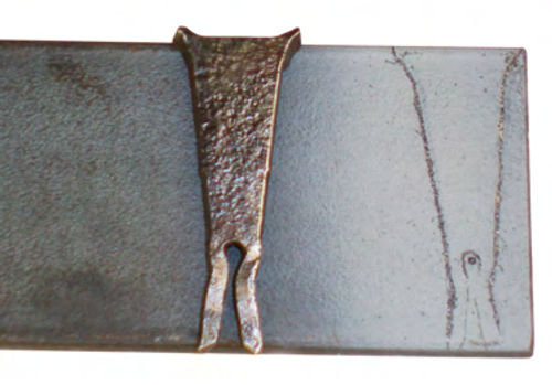
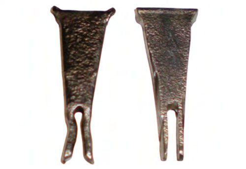
Next was the task of locating stock from which to make the new weight. A section of 2” wide by 5/16” bar stock was found in the shed, and even though it was slightly thinner than originally planned, it might just work. Remember that if the calculations are correct, 3/8” thick would be slightly heavier than needed. A light coating of paint was sprayed on the bar stock, then the old weight’s shape was scribed into it. Photo 9 shows the results. The location where the legs begin has been center punched and will be drilled out with a 7/64” drill bit. That appears to match the original. The drilling will be done first, and then the piece will be cut from the stock. A 3” cutoff wheel mounted on an air grinder was used to cut out the shape and split the legs. Further Shaping was done on a bench grinder, and the rough edges knocked down with a wire wheel until it fit nicely into the rotor’s vent hole. Photo 10 shows the new weight next to the old one.
Testing the New Weight on the Rotor
The new weight was positioned in the vent hole located behind where the wheel weight had been taped. Tape was again used to retain it until the location and amount of weight were determined to be correct. While hard to believe, the new weight and location appear to be right on target. Normally this is not the case. Typically you can expect to remove the weight several times to lessen weight, or even replace it with a heavier one.
The weight is now ready to be secured by bending over the legs. In Photo 11 you’re looking inside the back of the rotor where the legs of the weight are protruding through the bottom of a vent hole. The same drift pin that was used to remove the old weight is now securing the new one. The rotor was held in the jaws of a bench vise, with wooden paint stir sticks protecting both friction surfaces. An old bolt was wedged up against the weight, keeping it snugly in place while the legs were being bent over. The last thing you want to hear is the weight clinking around in the rotor when the vehicle starts to move, so make certain it stays snug.
A Final Test
It is tempting to start putting the vehicle back together, but if anything changed when the weight’s legs were bent over, now is the time to catch it. I certainly don’t want to repeat the entire process. So the bearings were reinstalled in the hub, and centered up on the cones as before. Again all checked out good. Now it’s just a matter of installing the rotor on the vehicle, and placing the pads and caliper. If the bearings haven’t been packed recently, this is a good time to take care of that task, and then proceed to the other rotor.
So What About the Left-Side Rotor?
While the right side was targeted because of a vibration that emanated from that wheel, the left rotor would certainly also be checked. As it turned out, there was a balancing weight in place in one of the rotor vent holes, however this rotor’s balance checked out fine. Spinning it four separate times, it stopped in a different location each time; as well it could be stopped in any location, and wouldn’t roll.
A Safety Note: Once finished, and the brakes are completely reassembled, make certain to pump the brake pedal several times before attempting to move the vehicle. In the event a caliper piston was pushed back into its bore during removal, this will reestablish a firm brake pedal.
If You Don’t Have a Balancer…
TheElCamino’s vibration is gone, and the motorcycle tire balancer performed exactly as I had imagined. The only negative thing I will mention about it is that the set screws used in the tapered cones were of poor quality. Whether using a metric or fractional Allen wrench, they both slipped. I replaced them with set screws purchased from the local Ace hardware for 88¢ each. Problem solved.
If you don’t want to purchase the balancer used in this procedure, but still wish to check your hub-typerotors, there is an option. You can actually use the vehicle’s spindle. Clean the wheel bearings, races, and spindle removing all the grease; then spray the bearings with WD40, or similar light oil. The bearings would then be placed back into the hub, and slid onto the spindle, leaving the hub seal removed. Replace the washer and nut, and snug very lightly by hand. With the vehicle’s spindle sitting level, you can now proceed with checking the rotor as described in the text. Remember to again clean the wheel bearings removing all the WD-40 before repacking them. This method will work, but will not be as precise. It certainly should be considered a distant second choice.
What About Solid Rotors or Those With a Large Center Opening?
Solid rotors will be found on many smaller vehicles. They can be one-piece and built with the hub included, or hubless, and simply slide over the wheel studs on the vehicle. These are known as “Hat Style” rotors.If you desire to check a “Hat Style” rotor, a tire bubble balancer is usually the best tool to accommodate its large center opening. This is true regardless of whether it’s the solid or vented design.

Most solid rotors offer few problems, being fairly well balanced. The hub mounted variety can be checked as we did using this Harbor Freight balancer. However, correcting an unbalanced solid rotor will be more challenging as there may be little or no option to welding weights on it. Brake caliper and wheel clearance must be kept in mind if weight is added. Usually, if it’s not too far off, removing weight is the best approach.
Tools Used In This Project
• Your basic hand tools & bench vise
• Cinder block & drill bits (to check tire runout)
•Wire brush
• Air-powered cut off tool with 3” abrasive cutting wheel
• Bench grinder
•Chalk or something similar to mark the rotor
• Masking tape & a few old wheel weights
• Scale (postal size)
• Harbor Freight balancer #98488
•Rotor Measuring tools: Micrometer and clamp-on dial indicator (a machine shop can also do this for you).


