
Tuning Up A ’39 Ford V-8, Pt. 3
Time to Install Our Plug Wires and Distributor & Check Them. Then We’ll Start the Engine and Go for a Road Test.
WE’VE BEEN WORKING on a ’39 Ford equipped with a flathead 221 cid V-8 that ran rough at times and barely hit 60 mph. There were 15 images with the first two installments, so we’ll start here with Photo 16.
Plug Wire Installation
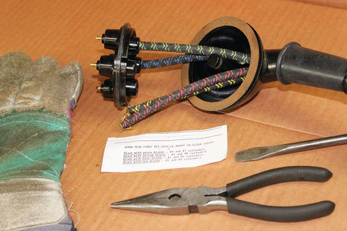
Feed the new plug wires through the plug wire looms. Slip the rain boot over the four wires. This procedure may be awkward. Try applying “Sil Glyde” (available at NAPA or CarQuest) over the plug wires one at a time. Feed the wires into the tube, then through the distributor cover and a new distributor cover gasket.
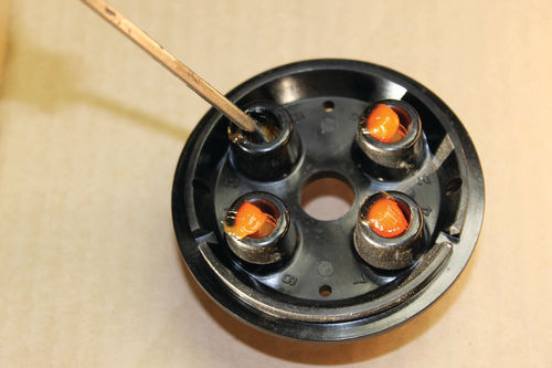
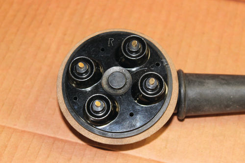
Guide the wires around the distributor cover center post. Route the wires to their respective cylinder terminals. See Photo 16.
Apply silicone lube into the distributor cap plate plug wire receptacles. See Photo 17.
Note: Ford V-8 cylinder numbers are 1, 2, 3, 4 on the right bank (from driver’s seat) and 5, 6, 7, 8 on the left bank.
The distributor contact plates are marked accordingly. For example number 4 cylinder plug wire will be connected to the #4 contact receptacle in the right distributor contact plate (looking from driver’s seat).
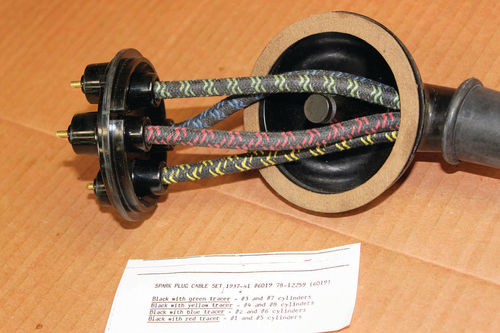
Route the plug wire around the cover post to minimize kinking. See Photo 18A
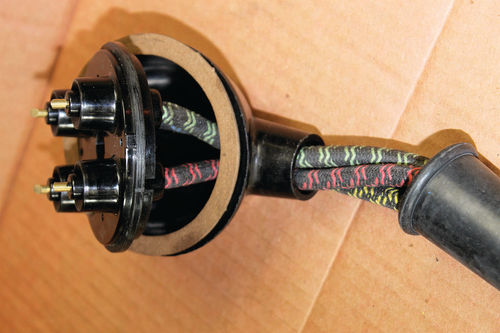
When installing the plug wires into the distributor contact plate, be sure the terminal connector “snaps” into place. Tug on the plug wire after snapping it into place to ensure that the plug wire terminal is seated. See Photo 18B.
In some instances, the plug wire terminal will not snap in. In these cases, file the edges so the terminal tangs will snap into place. Be aware that this can be very tedious work.
Align the notches between the cover and distributor plate, walk the wires back into the cover, rain boot, and plug wire looms. See Photo 18C.
Insert the distributor contact plate over the cover center tower post. See Photos 18 C and D. Install the rubber retaining washer. See Photo 18D.
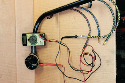
Now check the “ohms” from the distributor contact plate lugs to the plug wire tip. The resistance should be near 0 in each plug wire. Up to 0.3 ohm is OK. This is the plug wire resistance.
Using a digital ohm meter, you must confirm all plug wires will be mechanically and electrically connected.
If this isn’t checked you may experience ignition misfire under cruise and heavy load conditions.
If there’s any arcing (gaps), you must correct these conditions before distributor installation onto the engine. See Photo 19 for final ohm checks.
Spark Test, Bench
The last distributor and wiring check is a bench test for a good fat blue spark at least 1/4-inch long.
Install the covers/distributor contact plates, with the plug wires installed onto the distributor housing. Assemble the distributor contact plates’ Leave the coil off. Recheck the rotor gaps as previously outlined. See Photo 6 (April issue).
After the rotor gap checks, install the coil on the distributor top using a light coat of gasket sealer (Permatex Gasket Maker, item #81160) on both sides of the gasket. Wipe off goobers.
Attach a primary lead, with an alligator clip, from the 6-volt battery (-) terminal to the coil input terminal (-).
Connect an alligator test lead from the coil (+) to the distributor primary input terminal. Attach a second alligator clip test lead from a distributor body ground to the 6-volt battery (+) terminal.
If there’s a spark when connecting the test leads, twist the distributor shaft blade to open both points (no spark).
Direct any one plug wire to the distributor body. Hold it 1/4-inch from the body. With this hookup, twist the distributor shaft blade clockwise looking at the backside of the distributor. Twist fast. You should get a nice 1/4-inch blue fat spark to the distributor body ground from the plug wire tip as you twist the shaft blade.
As you continue twisting the blade, start to move the spark wire away from the housing until you’re up to a 3/8-inch spark. At that distance you should still get a nice fat blue spark.
If the spark is short (less than 1/4-inch) and orange, replace the coil and test again as described above.
Even though the coil ohmed out OK on the bench, it’s possible the coil is not performing by producing a 1/4-inch spark. Replace the coil.
If the spark is still weak with a new coil, recheck all your previous bench electrical work. Ohm the points for continuity (0 ohms) and open circuit (points open) insulation (more than 20 megohms). Watch the condenser charge up from 0 ohms (points closed) to points open (20 megohms).
My website milttheinstructor.com shows how to make ohmmeter tests.
Distributor Installation Special Tool
Make a guide bolt. Cut off the head of a 5/16 coarse thread bolt by 3/4-inch. Saw a slot in the bolt. This tool will make the distributor installation easier.
Installation: Remove the distributor covers and wiring looms from the distributor body.
Line up the offset blade shaft with the offset slot on the engine.
Apply a light film of Permatex gasket sealer on one side of the distributor gasket. Set the gasket on the block.
Install the distributor over the guide bolt, aligning the distributor shaft blade into the block slot.
Make sure the distributor body is seated onto the gasket. Install the other two bolts (5/16 NC x 3/4” long with lock washers).

Make sure the condenser is grounded. Snug up the bolts to hold the distributor in place. Remove the guide bolt and install the 3rd bolt. Torque bolts evenly.
Leaving the key off, crank the engine while watching the rotor spin. Ensure there’s no mechanical binding or metal clicking sounds.
Plug Wiring Looms: Install plug wire looms making sure the cover notches line up in the distributor housing and the wire loops snap into place.
Crank the engine again (key off) to ensure rotor tips are not clicking and/or hanging up on distributor contact plates.
Spark Test In Car: Check the terminals at the ignition switch and at the dropping resister. They must be tight.
Note: On some later-than-1940 installation or coil conversion kits, the dropping resistor may be mounted on the coil on the cylinder head. In either case, use only one resistor. The dropping resistor usually measures around 0.7 ohms.
Connect the main wiring lead from the dropping resistor on the inside firewall to the top of the coil terminal.
With all plug wires disconnected, turn on the key. Hold one plug wire 1/4-inch from the cylinder head. Crank the engine for five seconds. You should see a 1/4- inch fat blue spark. If so, all’s OK.
Reinstall the spark plug wires onto the previously installed spark plugs.
It’s Time to Start the Engine
Check the oil and coolant levels and place a fire extinguisher near the car.
Turn on the key. Pump gas by opening throttle two times. Watch for a strong squirt to ensure the carburetor has gas.
Pull choke out to close. Open gas pedal to 1/4 open, crank engine, and push choke inward to 1/2 open after one second of cranking. Start up should occur within 2-5 seconds.
As the engine starts up, hold throttle open around 1/4. Let the engine smooth out and rev up. Watch the oil pressure gauge. It should go up to at least halfway or more.
If the engine is sputtering at a slightly open throttle to rev up, push choke inward slightly. Listen for smoothing out and clearing out the extra gas (slightly rich mixture).
If the engine “starves out” during startup, repeat start-up with a full choke for two seconds, during the initial crank. After startup with 1/4 throttle, push choke inward to around 1/2 open. As the engine revs up or as it sort of tries to rev up, pull choke out slightly more to richen the mixture. Listen for a smoother rev up.
Let the engine warm up, then we’ll perform some running tune-up tests and adjustments.
Running Tune-Up Tests
Spark Test, Running: Hold throttle open and rev up to a steady 1000 rpm. Short out 1 plug at a time. Listen for an rpm drop (around 50) holding the throttle steady. This is your spark check test. See Photo 20.
Is the carburetor dripping? At idle look down the carb throat (use goggles). The top of the throttle blades should be dry at idle.
If wet, look for dripping out the main jet discharge nozzles, flooding and/or drip out the accelerator pump nozzles.
Rev engine to a steady 1500 rpm. Watch for a smooth fuel discharge pattern out of the carburetor main jet nozzles.
At idle, momentarily “tromp” on the throttle and note if there’s any hesitation during rev-up. If hesitation exists, choke slightly and repeat the tromp test.
If hesitation is gone with a slight choke during tromp, the mixture main circuit may be slightly lean.
If lean, recheck float level (is it at specification?) and the accelerator pump. If hesitation still exists, increase main jet size “1 step.” Note: One step means increasing the main jet diameter 0.001 inch.
Engine Checks, Vacuum
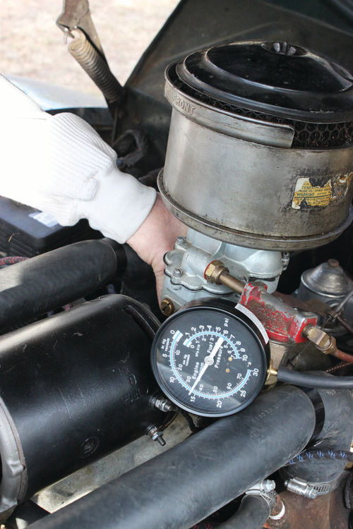
Hook up a vacuum gauge at the windshield wiper tube. Rev engine to a steady 2000 rpm. The vacuum should read around 18” or more at a steady 2000 rpm. See Photo 21.
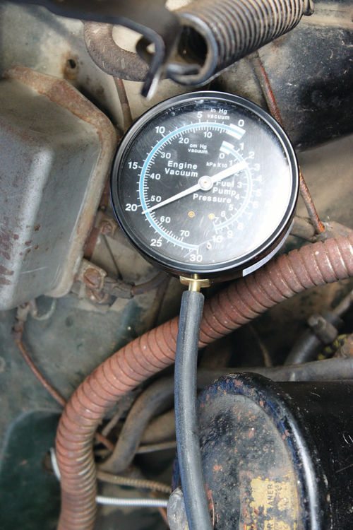
Quickly close the throttle from 2000 rpm. The vacuum should increase up to 24 or 25 inches during deceleration. If so, the engine is a good pump. See Photo 22.
If the vacuum is low at a steady 2000 rpm, like 10 or 12 inches, the exhaust system may be plugging up (sitting and rotting for many years). The quickest way to test the exhaust is to disconnect the pipes at the exhaust manifold flanges. Perform the vacuum tests again as described above.
If the vacuum readings are OK with the exhaust pipes disconnected, replace the muffler system.
Coolant Tests: During the engine run tests, watch the coolant temperature and oil pressure.
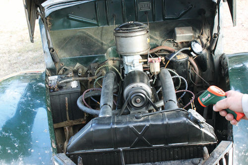
Using an infrared gun to take temperature measurements, the upper main radiator tank may read around 160° F on the outer surface. The coolant may be around 180° F. These results are all OK. See Photo 23.
If the coolant temperature is running higher, perform these tests again after road testing and/or cooling system service. Keep the radiator full of coolant.
Charging Voltage
Hook up a voltmeter on the vehicle’s battery and test the charging voltage with the engine revved to a steady 2000 rpm. After you’ve satisfactorily completed that, test the voltage at idle.
Oil Pressure Check: Watch the oil pressure to ensure it will stay up to half way on the dash gauge. The oil pressure may be slightly lower at idle.
Smoke Test: Tromp on the gas while watching for white smoke. If so, drive the car to see if smoke decreases.
If the smoke is black during tromping, the carburetor main circuit may be slightly rich. Take note, we’ll check more after the road test.
Idle Mixture: At idle with a warmed up engine, adjust both idle mixture screws outward to 3 turns open. Set the idle rpm to 400. Screw in one screw (only) watching for an rpm and vacuum gauge increase. Look for “peak” rpm and maximum idle vacuum. Continue screwing in and listen for an rpm drop.
This is the “lean roll” adjustment position. Open this idle mixture screw up (counterclockwise) back to the peak rpm point. This is usually around 1/2 to 1 turn from the lean roll position.
Perform the same adjustment on the other idle mixture screw.
This procedure will get you to the “best idle” point and a mixture balance between the two barrels.
Recheck the idle mixture, using the above adjustment procedure after the road test. Mixtures change with driving after setting for many years.
Conduct a Road Test
Safety Checks: Make sure your vehicle is safe to drive. This includes good tires, gear oil in the transmission and rear axle, and no dragging brake shoes.
Check the tire pressures and the condition of the steering system. Lube all grease fittings, fill up the steering box and make sure all bolts are tight. Check wheel bearings, steering tie rod ends and alignment (toe in). Make sure the wishbone ball (Ford) is tight.
Please review my article on “Inspecting a Collectible Vehicle” (Auto Restorer, August 2008). This article provides lots of detailed “what to do” checks.
Drive Checks, Part Throttle Acceleration: Take off with normal acceleration, shifting up from first to second at 20 mph and then shifting to high gear at 40 mph. Note hesitation and/or black smoke (someone must follow your car for the smoke check).
If hesitation exists during the part throttle acceleration tests, choke slightly and perform the acceleration tests again.
Full Throttle Acceleration: Open the choke. After takeoff with a part throttle, tromp the gas pedal to wide open. Let off and shift at 25 mph into second gear. Tromp again to wide open. Note smooth acceleration and no hesitation in second gear. Accelerate at WOT to 40 mph, then shift to high gear.
Also, note any pinging during these WOT acceleration tests.
Cruise Test: At 50 mph in high gear, steady speed, note any “holding back.” Choke slightly to see if speed picks up with a steady throttle. The mixture may be slightly lean, or the ignition timing may be over advanced.
Pinging: During the full throttle tests listen for pinging. If pinging exists, tighten the distributor vacuum brake bolt 1/2 turn.
This will promote a slight increased drag on the governor (advance) plate, retarding the timing slightly more during heavy load acceleration.
If pinging still exists, review the Ford Service Bulletins for factory specified adjustment procedures.
Vacuum Checks: At a steady 50 mph cruise in high gear the engine vacuum should be around 17 to 18 inches. As the speed is increased, the vacuum will drop at a steady cruise throttle.
If vacuum is low (like 8-10 inches) at a 50 mph cruise, the muffler system may need service and/or the engine condition needs analysis.
The engine may be partially plugged up with carbon in the intake and/or the exhaust valve and manifold ports.
Drive It: If there’s no knocking and the vehicle runs well, drive for 100 miles. Then change the oil and filter again. Fill up with 20-50 wt oil and don’t use additives.
Now perform the running tests outlined above once again.
Where To From Here?
Our ’39 Ford performed well in all the above tune-up and road test checks.
When the engine is cold, it starts up within two seconds of beginning crank. When the engine is warmed up, it starts in one second.
Now that all the “mechanicals” are done, corrected, repaired and adjusted, it’s your choice regarding cosmetic work. Do you want to go for show or touring? Myself, I like safe, durable touring.
Remember that your ’39 is 74 years old in 2013. Stuff happens and may break and/or change adjustments. So, always carry spare parts and be prepared for additional repairs and adjustments


