
Tuning Up A ’39 Ford V-8, Pt. 2
We’ll Do Some Resistance & Insulation Tests on Distributor Parts. And We’ll Get Plug Wires for This Underperformer.
WE’RE WORKING ON a ’39 Ford equipped with a flathead 221 cid V-8 that ran rough at times and barely hit 60 mph. There were eight images with the original installment, so we’ll start here with Photo 9.
Point Resistance & Insulation Tests
The distributor circuit breaker plate was cleaned with electronic contact spray and a toothbrush. It was air blown dry.
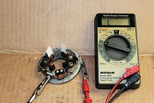
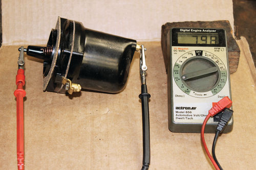
The points were tested for contact resistance (0 ohms closed). Open circuit insulation (points open) measured out to 20 megohms proving no insulation breakdown in the Bakelite blocks. See Photos 9 and 10.
If the point and insulation tests do not pass the ohm checks, try drying the plate in an oven set on “warm” for one hour. If the plate still does not pass the ohm check, replace it.
The condenser measured 20 megohms indicating good insulation to ground (no current bleed to ground).
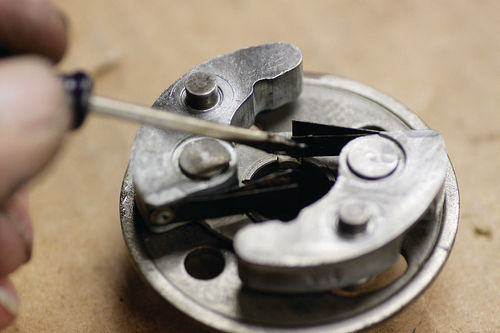
Governor Advance: The governor plate pivot pins were oiled (motor oil) and the governor spring fingers lightly greased (moly, general purpose). See Photos 11 and 12. Once lubricated, the mechanical advance plate worked (rotated) very smoothly.
Moly general purpose grease was applied to the eight-lobe cam.
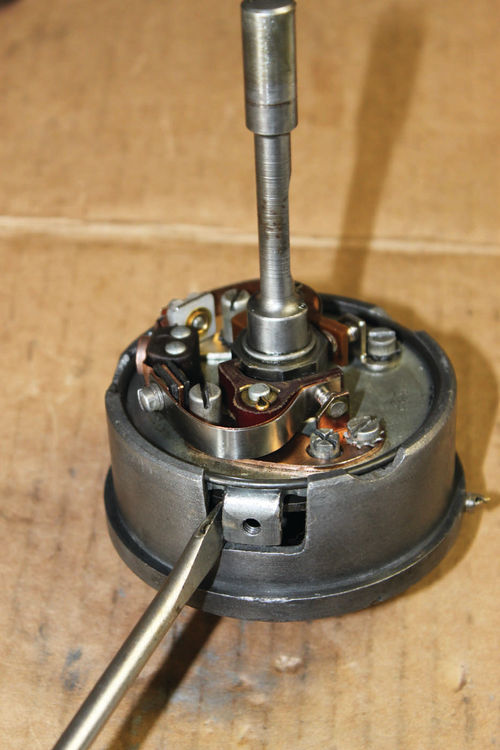
Distributor Point Plate Installation: Install the distributor plate into the governor body. Install the snap ring. See Photo 13.
Distributor Assembly: Install the governor body into the distributor housing. Recheck end play, rotor gaps and governor body fit.
The previously installed new points were gapped near spec (14-16 thousandths). However, both contact points had to be realigned and re-gapped.
I gap new points on the “high side” beyond spec to allow for point rubbing block wear-in. Therefore, I adjusted the points to 0.017 inch, which is just 0.001 inch over the recommended spec range (0.014-0.016 inch).
Again, the point contact resistance was measured at 0.0 ohms on one point.
The other point resistance was around 4-6 ohms (a no-no!). This contact point was sanded with 150-grit wet/dry sandpaper and cleaned with contact cleaner. The measurement then was 0.0 ohms. See Photo 9.
The insulation resistance measured out at “1” on the 20 megohm scale. This proves there’s no chance for current leakage to ground.
Vacuum Brake: Install the vacuum brake with the leather slot 90° to the previous groove. We will adjust the vacuum brake bolt during the road tests, if necessary.
Coil Checks: With the coil removed from the distributor, test the primary and secondary resistance of the coil.
The primary resistance will usually measure around 0.5 ohm.
Hook up a digital ohmmeter to the primary input (top) terminal and the primary coil spring (bottom) contact. Select the 0-200 ohm scale.
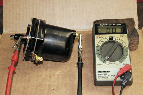
If the resistance is over 1.0 ohm replace the coil. If the primary circuit is open (1 or Ol on the 200 scale) replace the coil. See Photo 14.
The coil secondary resistance is measured by hooking the ohmmeter from the primary contact (top terminal) and the secondary contact (button that contacts the rotor). Select the 0-20k scale. Most Ford 6-volt coils measure around 6000 ohms. See Photo 15.
If the coil secondary resistance measures under 4000 or over 10000 ohms, replace the coil.
Bear in mind ohm checks are bench checks only. You are looking for obvious shorts, high resistance, and/or open circuits. The ohmmeter only flows a few milliamps of current during the ohmmeter bench tests.
In operation (on the car) the coil gets warm to the touch. This is normal.

The primary circuit current flow on the vehicle is around 4-6 amps during operation. You should be able to leave your hand on the coil surface while the engine is running. If the coil does get hot to the touch and you cannot leave your hand on the coil during the running tests, replace the coil, after all of the bench rebuilding is completed.
Plug Wires
Purchase new plug wires and new rain boots. Clean and paint the plug wire tubes.
If you’re into showing your car, the Ford V-8 parts houses can supply show quality-correct plug wiring, color coding, and terminal clips.
Plug Wire Resistance: New “stranded wire” plug wires should measure 0 ohms (continuity).
Check the “ohms” on each new plug wire. The resistance should measure 0 (continuity) from end to end. You are confirming continuity through the connection between the connector terminals and the wire.
If you’re installing a “universal” wiring kit using “suppression” or “resistance” wire, the resistance on a new wire will measure around 3000 ohms per foot. These plug wires will perform just as good as original style stranded plug wires, using a “strong” new coil.
Caution: If any of the resistance in one suppression plug wire is above 30,000 ohms on an old plug wire, replace with a new set of wires and connectors.
If the plug wire resistance is left above 30,000 ohms on suppression wires, ignition misfire will result.
Next: We’ll install the spark plug wires, run more tests and take the car for a test drive.


