
Tuning Up A ’39 Ford V-8, Pt. 1
This Car Could Barely Hit 60 mph and Ran Rough at Times. So We’ll Test Some Systems That Could Be at Fault.
OUR PROJECT VEHICLE is an unrestored ’39 Ford equipped with a 221-cubic-inch flathead V-8 producing 85 horsepower. The odometer shows 70,670 miles. The odds are that the engine has never been apart.
Concerns: The owner complained, “no power at higher speeds.” This car would barely make 60 mph.
The car “starts up OK” and “seems to run OK” at lower speeds.
Recently, the owner had the plugs, points and condenser replaced. The starter had been rebuilt.
The carburetor was rebuilt by the Carburetor Factory at 7806 Antelope, Citrus Heights, CA 95610; carburetor factory. com; .
Our Approach to the Tune-Up
How about taking a closer look at symptom causes of poor performance at higher speeds? It takes more than replacing parts to get acceptable performance.
The approach encouraged here includes battery and cable service, engine condition tests, ignition system repair (plugs, wires and distributor rebuild), fuel system service (tank, fuel line, pump, filter and carburetor), a manifold vacuum measurement, and road tests.
I also strongly recommend all serviced components be installed and adjusted to factory specifications. You will be surprised at the improved performance!
Further, I recommend all the above items be tested, repaired, and/or adjusted to specs. You want to be sure all systems are performing right before start-up and road testing.
A “shotgun” diagnosis doesn’t work!
The Starter System
The cranking sounded fair, but not up to “snuff.”
The battery rest voltage was only 6.2 volts. Full charge is 6.4 volts. The cranking voltage was 5.0 volts.
A large voltage drop of 0.4 volts was measured across the starter solenoid, (very poor). The ground voltage was 0.1 (very good).
At this point I decided to clean all the battery and ground connections.
The starter cable was tight on the starter; however, the starter inner nut was loose in the starter housing (a no-no).
The inner nut was tightened and the outer nut was re-tightened over the cable.
All cable ends and the battery posts were removed, cleaned, and re-installed.
The starter battery system now sounded very energetic!
Servicing the loose starter stud and the rusted solenoid connections cured the sluggish cranking sounds. The starting system now sounds energetic even with a marginally OK battery voltage (6.2).
Engine Condition
The oil had been changed and was clean.
Cranking compression on the cold engine varied from 80-95 psi. This is fair and good enough to continue with the tune-up.
After startup and warm up the cranking compression was tested again, measuring from 95-105 psi. Very good! The specification is 100 psi.
Note: Engine specifications are listed in the 32-41 Ford Shop Manual, Service Handbook, 1940; licensed reproduction by Ford Motor Co.
After startup the oil pressure gauge showed mid scale (around 30 psi) and there was no rod bearing “chirp” at the first startup.
This flathead V-8 had a nice consistent (quiet) clicking at the valve lifter tappets after completing all service and bench tests.
I recommended the oil be changed again at 100 miles just to help clean up the engine innards.
I do not recommend oil additives, kerosene or diesel fuel for internal cleanup or performance improvement! New clean motor oil is better.
I recommend 20-50 wt detergent oil. A zinc additive is OK, but unnecessary on a stock engine.
Question: What did we do in the old days (prior to 1942) without zinc? Stock flat tappet cam engines went thousands of miles without zinc, on clean “non detergent” oil!
Ignition
New spark plugs had been installed. I cranked the engine with the key on. The spark was fair but would only jump a 1/8-inch gap (not good enough).
During the compression check, I “read” the plugs. Four were very white on the internal porcelains. Very good. Two plugs were dark, but not sooty. Two were very dark and the internal porcelains were wet. This indicated the two plugs were “fuel fouled.”
None of the plugs were black and sooty (rich condition). This indicated the carburetor main circuit air/fuel mixture was in the “ball park.”
Light tan to light orange on the internal spark plug porcelains shows normal air/fuel mixtures. The plug wires were old and stiff. They were replaced at a later date.
The gap on all plugs was 0.025 inch (at specification).
“Never seize” was applied to the threads, and the plugs were re-installed and torqued to 1/8 turn past washer seat contact.
Note: New plug wire installation is critical on this Ford V-8. This process is outlined in detail later in this series. (Old plug wires “arc” inside the wire loom tubes.)
After startup I measured the firing voltage at each plug at 1500 rpm in neutral (cruise simulation) and during tromping on the throttle (momentary heavy engine load). Six cylinders were showing 10 to 15 kilovolts plug firing voltage at simulated cruise (1500). The same six cylinders showed moderate plug firing voltage increase (around 15 kv) during throttle tromp. Two cylinders showed 25- 30 kv during tromp. These are the same two plugs that were dark and wet!
Aha! We’re starting to discover why there’s no power. “Replace these two plugs; that’s all that’s wrong!” you guess? Nope, we must dig deeper to find other possible causes for no power.
The firing voltage (kilovolts) was measured with a Smart Tach+ from General Technologies Corp. and available through CarQuest Auto Parts.
The “base timing” was set at 12° BTC on the distributor which is a whopping 24° on the crankshaft!
On ’39 Fords the base timing spec is 4° on the crankshaft.
Note: Each mark on the distributor timing plate is two distributor degrees.
The point dwell measured 42° at idle at 2000 rpm.
The dwell spec is 74 to 80%. This calculates out to 44° to 48° on an 8-lobe distributor. The point gaps were adjusted close to spec.
Fuel System
The car owner had had the fuel tank cleaned. A new flex line was installed to the fuel pump.
The pump pressure measured 31 ⁄2 psi. This is very good.
The fuel pressure specification is 3 to 5 psi.
The flow showed strong squirts during cranking with the fuel line inserted into a plastic bottle.
These measurements confirm good fuel system performance up to the carburetor.
The carburetor accelerator pump showed strong steady fuel streams upon sudden throttle opening, engine off.
Start-Up
The engine started up within five seconds of beginning cranking. The engine “smoothed out” some, but ran “rough” at 2000 rpm.
Base Timing: At this point the base timing was adjusted from 12° on the distributor back to the second mark (4°) from the top on the distributor (8 crankshaft degrees). See Photo 1.
Still Missing: The engine smoothed up some more, but still “seemed to miss.” We revved up the engine in neutral to wide open throttle, (momentarily) but the rpm would not go above 3000.
At this point we measured the plug firing voltage again, as outlined above. As we also discussed, two plugs still had high firing voltage, but we had not yet discovered why.
Carburetor Run Tests: Carburetor running checks were performed. There was no main nozzle “drip” at idle and the top of the throttle blades were dry at idle (normal).
Revved up to 2000 rpm, the main circuit nozzle discharge was even when looking down on both barrels. The fuel nozzle discharge looked “vaporized.” Remember to use goggles during this test.
At a steady 2000 rpm, the carburetor was choked slightly. The rpm dropped off, indicating a good A/F mixture.
Idle Mixture: The idle mixture screws were “balanced” and the idle speed was 500 rpm.
At this point I decided the rebuilt carburetor was performing very well.
Generator: The rebuilt generator was hooked up wrong. The regulator ground wire was connected to the generator field (F) terminal; the regulator field wire was connected to the generator ground (G).
The voltage at the generator armature post measured 0 with the engine at 2000 rpm.
I recommended the rebuilt generator be re-checked. The voltage regulator may also have to be changed.
The battery voltage held at 6.1 volts revved up confirming the charging system was not performing, although the battery was fair at 6.1 volts.
A reading of 7.2 volts at the regulator “bat” terminal is normal. A low battery voltage (6.1) should climb up to 6.4-7.0 during the first few minutes of running on a good battery. The generator was not charging.
Distributor Removal, Inspection and Service
At this point in the tune-up process, I had to “bite the bullet” and remove the distributor.
There were no “rain boots” between the wire looms and the distributor covers.
Someone had told this Ford owner that boots were not necessary. Baloney!
Note: All the parts missing or needing replacement are available through Ford V-8 parts vendors.
There were no distributor plate/cover gaskets.
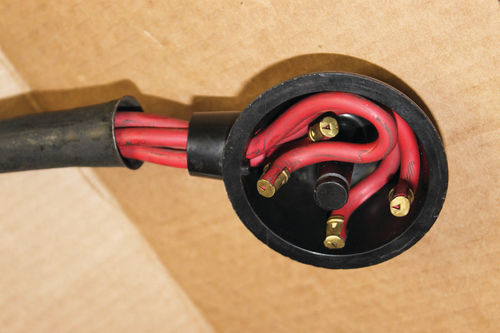
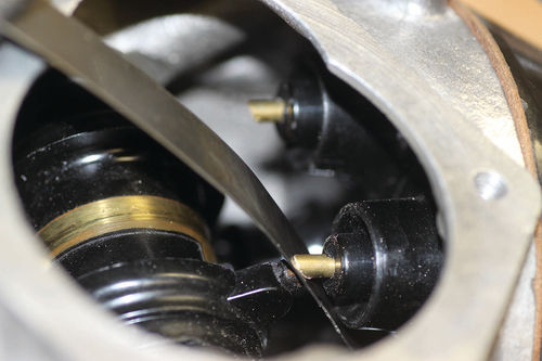
The plug wires easily pulled out of the distributor plates. One plug wire, I believe, was previously disconnected, a clue to the rough running and no power. (See Photo 2.)
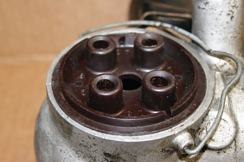
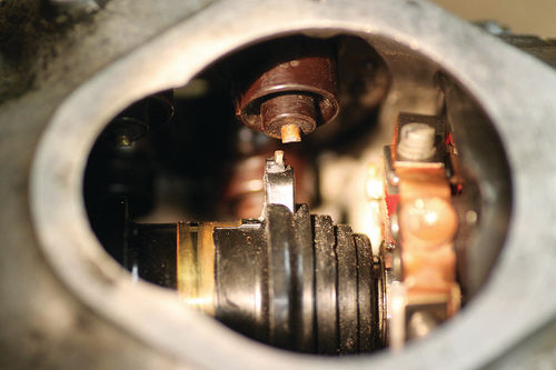
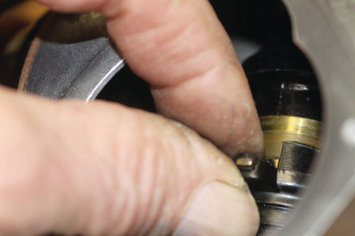
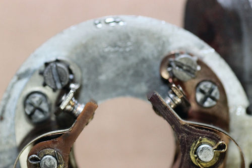
The distributor plates were stuck and not seated in the distributor housing casing (a no-no). One side was cocked and not seated (Photo 3). This created a very misaligned cap and a 1/8” rotor gap, a second clue regarding rough running that can also result in ignition misfire. See Photo 4.
After removal, the distributor shaft was almost frozen.
New points had been installed and were gapped to spec (0.015 inch).
Upon disassembly, the mechanical advance and vacuum brake were not jammed. However, there was no gasket on the vacuum brake adjustment bolt. This could cause a minor vacuum leak.
I believe the plug wires, large rotor cap, and the disconnect on one plug wire were the main culprits to “no power at higher speeds.”
The distributor cam lobes were dry! In other words, there was no cam lube. This leads to excess wear on the point rubbing blocks.
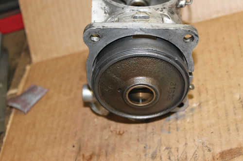
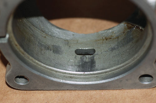
Disassembly: The distributor housing was slightly warped making the innards difficult to disassemble (Photo 5A).
The distributor was completely disassembled and cleaned in carburetor cleaner, except the circuit breaker (point) plate.
Distributor Housing: After cleaning all parts, the first step is to file the distributor casing to remove the causes for binding using a round crosscut file. File off the bright areas in the housing, using a 3/8 crosscut round file. See Photo 5B.
Deburr and buff the governor advance housing. File the edges and buff the body and advance housing “high spots.” Continue checking for binding.
The governor housing should easily slide into the distributor housing. Clean and then re-install the governor body with the shaft and the rotor into the distributor housing.
Re-fit distributor plates: Install one side distributor plate to measure the rotor gap. The rotor in this case had around a 1/8- inch gap (way too much).
The other distributor plate was installed but cocked as mentioned above. This rotor gap was misaligned and measured over 1/8 inch as shown in Photos 3 and 4. Yuk! Ignition misfire was most likely, especially under higher speeds and heavy engine load!
A new distributor contact plate and a good used distributor contact plate were installed. The rotor gaps were now measured at 1/64 inch. See Photo 6.
Note: One lug on the new distributor cap was barely touching the rotor tip, a no-no. This lug was filed to gain the 1/64 inch gap.
Caution: New old stock (NOS), reproduction and used parts must be selected, fitted, and measured during the distributor assembly checks as discussed above. The production tolerances vary considerably.
Fit the distributor contact plates into the distributor casing. In this case the aluminum housing ridges and the distributor contact plate edges were deburred using 80-grit strip sandpaper. Finally, they “pushed in” easily without sticking.
The end play in the distributor shaft was adjusted to 1/64 inch (0.015 inch). This allows for heat expansion See Photo 7.
Point Alignment: At this point, align points so the contacts are concentric and square. See Photo 8.
Next: We’ll test the points, get new spark plug wires, run more tests and take the car for a test drive.
And for more from Milt, visit his website, milttheinstructor.com. He specializes in tuning up everything from an early Model T to modern, computer-controlled cars and trucks.


