Restoring a 1976 Triumph Spitfire Part 8
The Project Has Fallen Behind Its Original Schedule, But It’s Now Coming to an “Odds and Ends” Stage.
“The best laid schemes o’ mice an’ men / Gang aft a-gley.”
I know nothing of the travails of mice, but this ever-true quote from Robert Burn’s ode “To a Mouse” often comes to me when my own schemes go awry, which is often, and this has certainly been the case for the Spitfire’s restoration.
The original intent was to have it completed for Triumphest this past September, but it became evident several months ahead of time that this goal was not going to be met. Life’s obligations and detours accumulated with misestimated timelines and parts difficulties to cause this self-imposed deadline to go unmet.
The revised goal is for the Spitfire’s completion before the garage’s summer temperatures again rise above 100° F. But I digress…
A Rag Joint Challenge
With the exception of installing the Spitfire’s engine and transmission, the Spitfire is in the “odds and ends” stage of its restoration, which in itself can consume large chunks of time. Items receiving attention these past few months included: the steering column; door panels and window felts; engine water pump, thermostat and oil filter installations; interior dash support recovering; installing the under-car brake and fuel lines; rear bumper modification and the replacement of the front suspension springs. A decision was also made regarding the wiring harness.
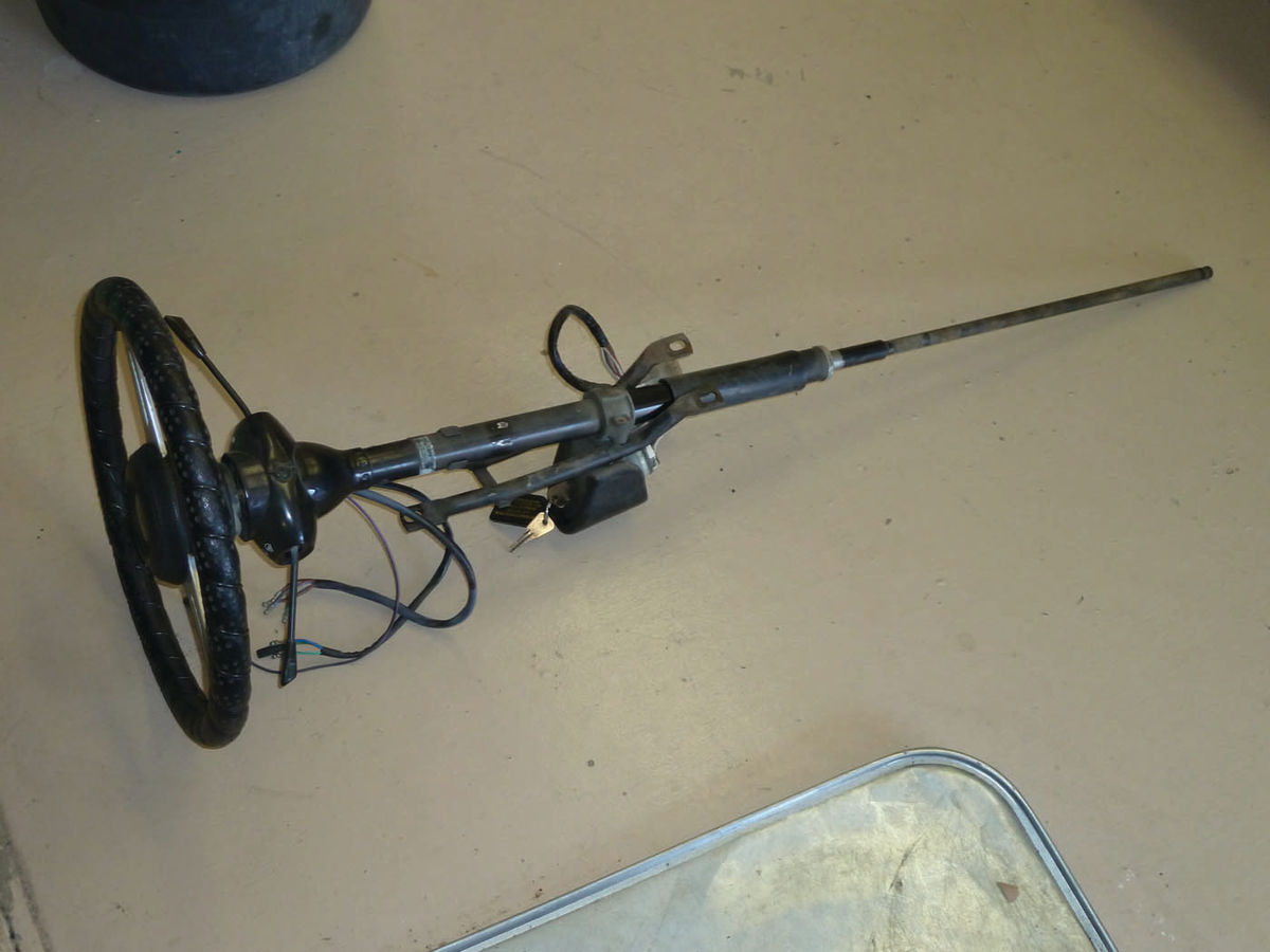
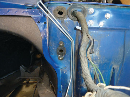
The steering column was removed for inspection and parts replacement. The job was straightforward and accomplished by disconnecting the rag joint between the steering column and the rack and pinion, detaching two brackets under the dash, disconnecting the wiring harness and simply pulling the column back and out through the firewall (Photo 1: Removed Steering Column). While out, the steering column was inspected and the felt bushings replaced from a kit sourced from The Roadster Factory. The firewall seal for the steering column was replaced (Photo 2: Firewall Seal) and the column reinstalled and adjusted via a sliding joint.
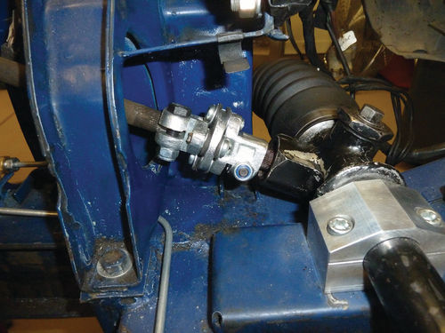
A difficulty arose, as per usual, with new part fitment. Although the original rag joint appeared to be serviceable, I decided to replace it for safety reasons. The replacement joint that I first obtained was a U-joint type that was longer and bulkier than the original rag joint. It interfered with a nearby frame bracket and did not allow the steering wheel to be rotated a full 360 degrees. A search of several suppliers finally resulted in locating a correct type rag joint from Victoria British that was installed with no further problems (Photo 3: Steering Rag Joint). After this, it was “just” a matter of hooking up the wiring harness, which was made somewhat trying by wiring harness colors that did not conform to those called out in the wiring diagram.
Fortunately, I had taken several pictures of the harness prior to disassembly and was able to complete the wiring connections by referring to them. (Always, always take pictures; the more the better.)
Working With Window Felts and Seals
Installing replacements for the worn-out window felts/waist seals were next. I had attempted to replace these earlier when working on the Spitfire’s interior, but had been defeated by the difficulty of installing the clips that held the new felts/ seals in place.
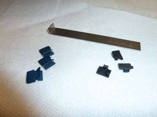
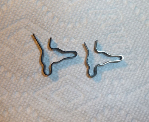
The Spitfire’s window felts/seals are held in place by seven spring metal clips that slide over the underside of the felt/ seal and the inner edge of the door window channel to secure them (Photo 4: Door Outer Waist Seal & Clips). There is little room to work the clips into place when the door window glass is installed, as it was in the Spitfire. (The Spitfire or perhaps I should say its passengers, enjoy the great luxury of roll-up windows.)
I had easily removed the old window felts and waist seals by using a putty knife to push down between the clips and the felts/seals to release the clips. (The old clips were later recovered from the door interiors when the door card panels were replaced.) Finding a tool that could be used to reach between the window glass and the seal to pull the clips up to lock the seal (or felt) into place was the problem.
An internet search brought a recommendation to bend the leading edge of a putty knife by 90 degrees into an “L” shape and then use it to pull up on the clips to set them in place. This was not workable for two reasons: 1) The blades tended to break before they could be bent the full 90 degrees, and 2) Even if successfully bent, the putty knife blades were too flexible and would bend and slip out before the clips were set.
I removed the door card panels in the hope that this might provide better access to the window seals, but this was not the case and I finally put the problem aside.
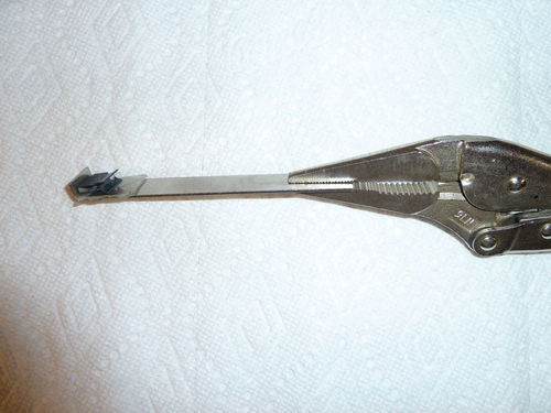

Returning to the task almost a year later, enlightenment belatedly struck. I remembered a specialized tool used on my TR3A to remove the headlight trim rims. It was “L” shaped and of sufficient thickness to resist bending when setting the clips (Photo 5: Headlight Rim Removal Tool and Clips). I modified this tool by attaching a pair of ViseGrips as a handle and adding a piece of double-sided tape to hold the clip in place while it was being set (Photo 6: Window seal Clip Insertion Tool). It worked very well, and window seals and felts were in place in about 20 minutes (Photo 7: Door Seals installed). Or should I say a year and 20 minutes?
Damaged Door Cards
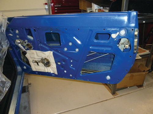
As mentioned previously, the interior door cards and moisture barriers were removed in an attempt to facilitate installing the window seals/felts (Photo 8: Moisture Barrier Removed).
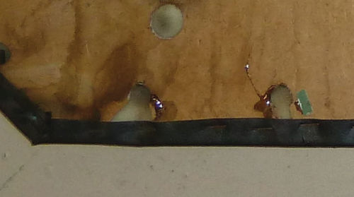
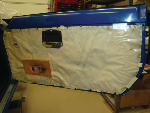
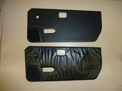
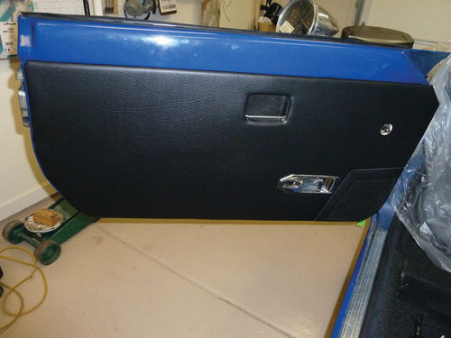
The cardboard backing for the door cards proved to be in very poor condition, and many of the attachment points for the mounting clips had torn away when the door cards were removed (Photo 9: Damaged Door Card Attachment Points). Attempts at repair with epoxy failed, and I decided to replace the door cards with new ones ordered from SpitBits. This is known as “requirements creep” (Photo 10: New vs. Old Door Cards). The moisture barrier was resecured with duct tape (Photo 11: Door Moisture Barrier) and the new door cards snapped easily into place (Photo 12: New Door Panel Installed).
Covering the Dash Bracket…Again
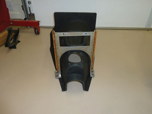
I continued the interior theme by next recovering the dash support bracket. This bracket is bolted to the Spitfire floor astride the transmission cover and attaches to the bottom of the dashboard (Photo 13: Dash Support Bracket). It serves to reduce dash shake and as a mount for the car’s radio. (The Spitfire will not have one installed.)
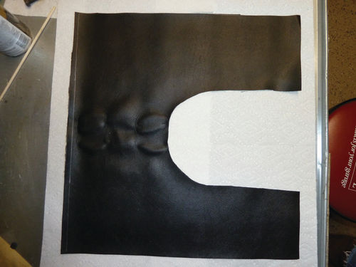
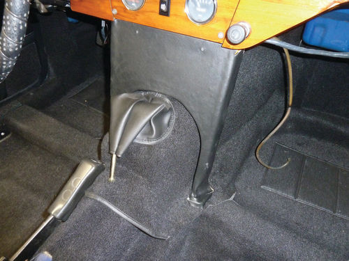
This bracket was originally missing from my Spitfire, but I was able to source a replacement from a fellow Triumph club member two years ago and had cleaned and recovered it at that time. I stored the finished bracket in the Spitfire’s trunk for future installation, but the summer temperatures in the garage proved sufficient to liquefy the headliner adhesive and the job had to be redone. I removed the old covering and cleaned the bracket of residue adhesive with 3M Advanced Adhesive Remover. New cover material was ordered from Rimmer Bros. and the old cover used as a template to mark and cut the new material to the required shape (Photo 14: New Cover Cut to Shape). The new cover was then glued to the bracket using 3M’s Advanced Headliner & Fabric Adhesive and the recovered bracket temporarily installed in the Spitfire (Photo 15: Dash Bracket in Place).
Blasting & Painting a Pump Housing
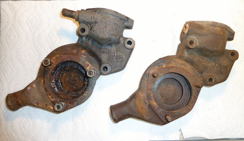
The Spitfire’s engine was now back from its rebuild (See Part 7, September 2017) and in need of a new water pump and housing. The original water pump housing was very heavily corroded, and I purchased a used housing from TSI as a replacement (Photo 16: Original Water pump Housing (l) vs. Replacement (r)).
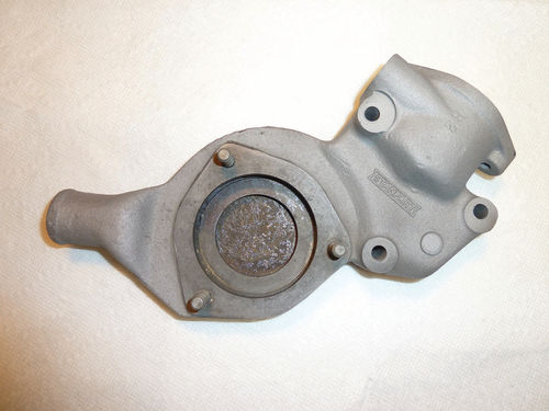
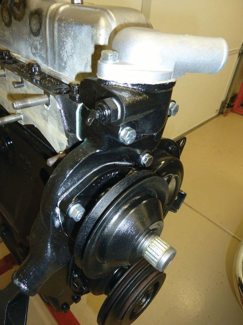
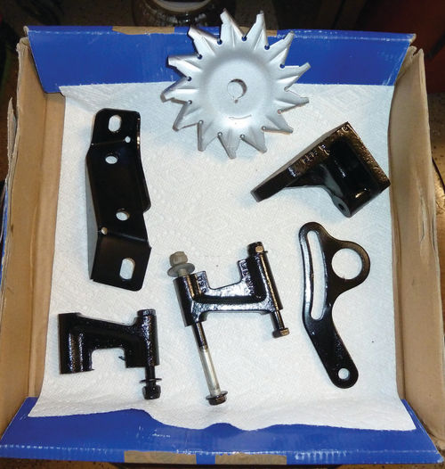
I used my Eastwood blasting cabinet loaded with aluminum oxide to clean the replacement housing of minor rust (Photo 17: Blasted Water pump Housing), painted it engine gloss black, and installed it with a new gasket, water pump and a 180° F thermostat (Photo 18: Water pump Installation). While the blasting cabinet was freed from its usual hiding place in the back of the garage, I took the opportunity to also blast and repaint the alternator support bracket (Photo 19: Painted Alternator Bracket).
A Tale of Two Oil Filters
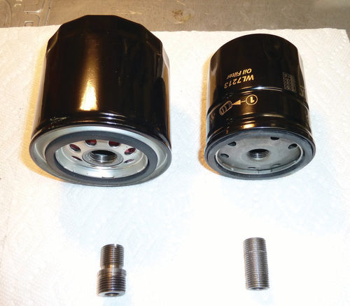
The next task was to be easy: Installing the engine oil filter. But as part of my continuing education in things Spitfire, I learned that the 1500 engine could be equipped with either one of two sizes of the spin-on oil filters, each with their own specific adapter. The introduction of air pumps and their associated brackets in the 1970s had reduced the available room for the oil filter and this necessitated switching to one of smaller diameter. These smaller filters used a 5 ⁄8” adapter to secure them to the block oil galley whereas the original, larger oil filters used a ¾” adapter. I was initially perplexed as the recommended oil filter that I had purchased was not compatible with the existing 5 ⁄8” adapter, buta visit to “The Triumph Experience” website (www.triumphexp.com) cleared up the mystery and I subsequently founda ¾” adapter, thus providing the option for either type of filter (Photo 20: Oil filter Options and Adapters). Since the Spitfire will no longer have an air pump, I elected to install the larger of the two filters.
Back to a Sports Car Bumper
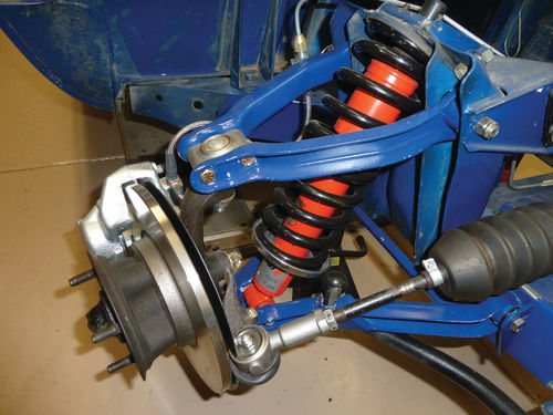
When the front suspension was rebuilt in Part 3 of this series (December 2016), I had reused the Spit’s original front springs. In Part 5 (June 2017), I described the installation of a 1” lowering block for the rear suspension. This combination would result in a mismatch between the front and rear ride heights of the Spitfire, causing it to sit with its nose in the air. This awkward posture was not my desired look for the Spitfire, and so a new set of lowered front springs were ordered from SpitBits and installed in place of the originals (Photo 21: New Front Springs Installed).
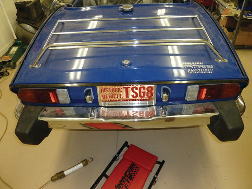
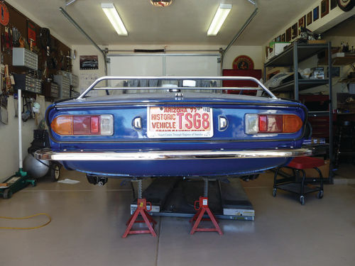
As per usual for me in these endeavors, the first spring replacement session took about two hours using the procedure outlined in the tech manual. For the second spring, I worked out an alternate procedure involving the removal of the trunion, and this installation took only 25 minutes. The lowered suspension will give the Spitfire a “sexier” appearance and improved handling. Something also had to be done about the Spitfire’s 5-mph rear bumper (Photo 22: 5-mph Rear Bumper).
I regarded this monstrosity, which, frankly, looked as if it belonged on the back of a dump truck, as an insult to the elegance of Giovanni Michelotti’s original Spitfire design.
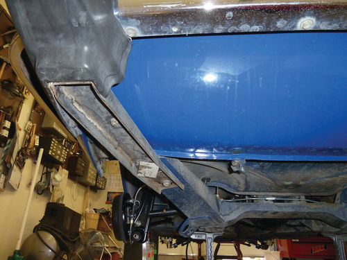
In late 1975, when this Spitfire was built, the Federal 5-mph rear bumper requirement was still new and British auto manufactures were scrambling to meet it. As a consequence, the Spitfire 5-mph rear bumper was a clumsy assemblage of oversized black rubber over-riders attached by large support brackets to the car’s frame (Photo 23: Over-rider Frame Bracket). These over-rider frame brackets also served as attachment points for a chromed C-channel that was fitted over the original Spitfire (non-5-mph) bumper. The good news resulting from this kludge was that the original, slim,
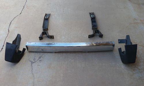
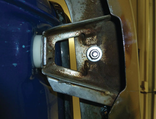
sports-car-like rear bumper was still in place and easily revealed by removing the rear bumper and eliminating the 5-mph modifications (Photo 24: 5-mph Rear Bumper Pieces). The chrome of the original bumper cleaned up nicely with the application of Wenol polish, and the holes used to mount the C-channel were hidden with chrome carriage bolts. Thick nylon bushings were used at the body mounting points when reinstalling the bumper to provide the required bumper/body spacing formerly afforded by the now-absent frame brackets (Photo 25: Nylon Washer Spacers). The unencumbered bumper gives the rear of the Spitfire a much sleeker look with the added benefit of a 25 lb. weight reduction (Photo 26: Remounted Original Bumper).
Modifying Some Brackets to Fit
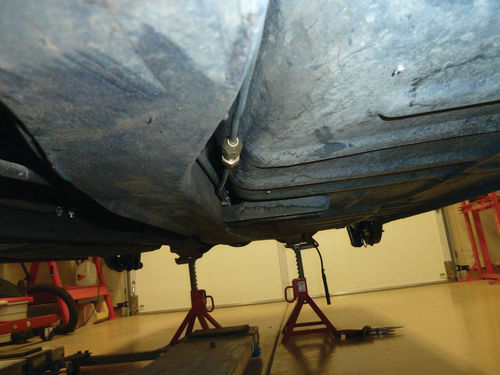
The charging and bleeding of the Spit’s master cylinder and brake lines has not yet been accomplished (part of the “schemes…gang aft a-gley”), but installation of the under-car portion of the brake and fuel lines was completed (Photo 27: Installed Fuel/Brake Lines). The pre-bent brake lines from Classic Tube required only minor work to install, and I elected to reuse the original fuel line after inspecting and thoroughly cleaning it. The new lines were secured with pipe brackets from Rimmer Bros. after reworking the brackets to fit. Both lines are intended to slip into the pipe bracket and be held in position once the bracket is snapped into place by rotating it up and into a hole drilled in the car’s frame. The Rimmer pipe brackets, although almost exact duplicates of the originals in size and shape, were too wide to fit into the frame mounting holes. The outer prong was also too long to allow rotation of the pipe bracket up into place as the space between the car body and frame was too narrow to allow it. (Almost certainly, the factory installed the brake and fuel lines before the body was set on the frame.) I narrowed the brackets with a bench grinder, shortened the prong, and proceeded to fit the lines with no further problems (Photo 28: Pipe Brackets with the Right Bracket Modified).
Sticking With the Original Harness
I had been vacillating for some time as to whether to replace or retain the Spitfire’s original wiring harness. Finally, after much consultation with the Oracles of Lucas, I decided to retain the Spit’s old harness. There were several factors in making this decision including, of course, the cost of a new wiring harness and the complexity of installing it.
A new harness would most likely result in fewer problems, but the insulation on the original wiring is still in good condition and several Triumph owners have advised me that they are still driving with their original wiring harness after 40+ years. (Just be certain to keep the grounds in good condition!) And, to confirm the decision, continuity checks of the Spitfire’s wiring have, so far, proven to be good. I will replace wiring connectors in the engine compartment since they have suffered from decades of assaults from dirt, wet and heat, and the fuse box on the firewall will be replaced. We will see if this proves to be a foolhardy decision.
Next Comes a Rebuilt Engine and Ford Gearbox
So, the list of items remaining to be accomplished on the Spitfire gets shorter, even if the timeline does not. For the next installment, the brakes will be charged and bled, the new fuse box installed and a start made on replacing the wiring harness connectors, but the major task will be mating the Spit’s rebuilt engine to the Ford 5-speed gearbox. This will be accomplished using an adapter kit and rebuilt transmission obtained from Frontline Developments (www.frontlinedevelopments.com). The effort will include modifying the Spitfire's bell housing to fit the adapter plate, replacing the worn-out parts of the clutch release arm and mating the engine and transmission. But that is for next time. That is, of course, barring another "a-gley"


