
Restoring a 1976 Triumph Spitfire Part 6
There Have Been More Problems With the Brake System and a Change in the Engine Rebuild Plans.
At the conclusion of the last entry in the Spitfire restoration series (June), the rear brake lines were being fitted in preparation for the installation of the axle half shafts and vertical links. As noted, however, there was an issue with the replacement left rear brake line being mistakenly fabricated with a metric connector instead of the required Imperial fitting.
The old brake line was still serviceable, and so, after cleaning it up, I attempted to install it. But a problem immediately presented itself. The male brake line fitting that was supposed to screw into the three-way union would not engage the union’s threads. Thinking that perhaps the new three-way had metric threads also, I removed it and confirmed that the union’s threads were Imperial. I was totally puzzled (not an uncommon state for me), but, fortunately, it was then that the editor forwarded a very timely letter from reader Bob Foley of Mansfield, Massachusetts (see pg. 28). Among the many insights that Bob provided was that the male portion of the brake line fitting can develop a slight bulge at the end as a result of being tightened and that, if the brake line is reused, this can prevent the fitting from properly engaging the threads of the union.
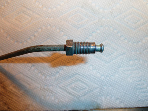
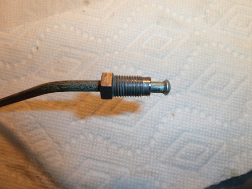
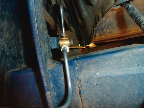
I examined the recalcitrant line under a magnifying glass. There was indeed a visible bulge (Photo 1: Brake line fittingbefore). Bob’s advice was to use a file to gently remove the bulge, which I did, (Photo 2: Brake line fitting–after) and I was then able to successfully install the brake line in the three-way union (Photo 3: Three-way union).
I must emphasize that the re-use of a brake line is not recommended, and should only be done after the line has been thoroughly inspected. In this case, I thought that the circumstances and the good condition of the brake line merited its re-use. It will be inspected again once the brake system is charged with fluid and bled.
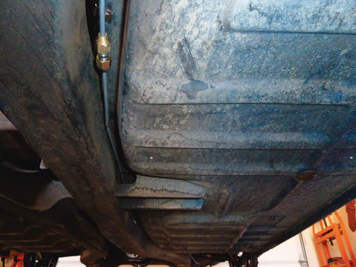
The under-car portion of the brake line forward to the firewall was also fitted at this time (Photo 4: Brake line under car). Securing this portion of the brake line with brackets will be done at the same time as the re-installation of the fuel line which takes the same path alongside the car’s frame.
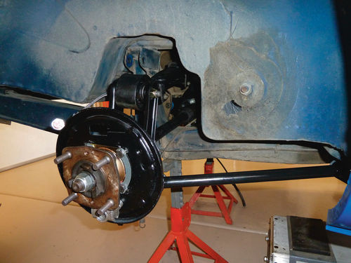
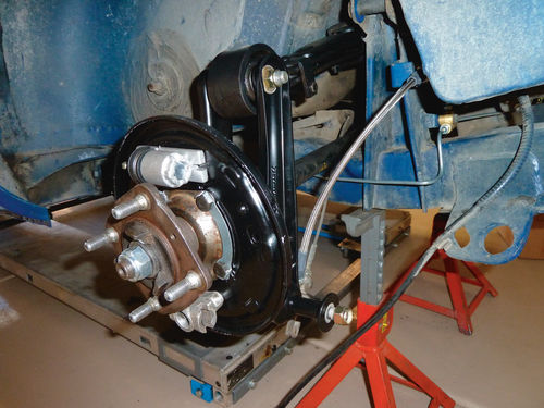
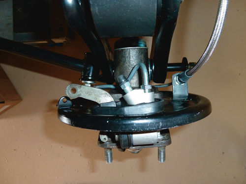
The Spitfire was now ready for fitting the axle half shafts, vertical links and radius rods. The procedure for this was straightforward. The upper attachment points of the vertical links were bolted to the ends of the rear leaf spring, the half axle U-joints secured to the differential flanges with four bolts each, and the lower attachment points of the vertical links then secured to the radius rods that were in turn fixed with bolts to the frame. This completed the axle installation (Photo 5: Axle half shaft and radius rod).
I had originally planned to install the shock absorbers at this stage, but decided to wait until after the brake system had been charged with fluid and tested as there is better access to the rear brake lines when the shocks are not in place. The fasteners for all of the suspension pieces, front and rear, will be torqued to factory specifications once the Spitfire is sitting on its wheels with the engine installed.
Working With the Rear Drums
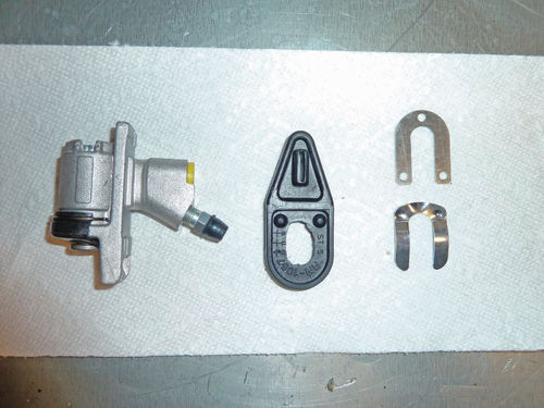
The time had now come for the reassembly of the rear brake drums. New rear brake shoes and brake cylinders had been sourced some time ago from TSI, and the original brake adjusters were cleaned for re-use. I installed the brake adjusters to the backing plate first (a mistake, I was later to discover) and proceeded to mount the brake cylinders. It was here that I encountered another problem. The rear brake cylinders on Triumphs and probably most other drum brake-equipped vehicles, are mounted through a slot at the top of the brake backing plate, and are held in place with a pair of interlocking flat springs that slide into a slot in the brake cylinder to secure it against the rear of the backing plate (Photo 6: Brake cylinder kit). Try as I might, I could not get the flat springs to slide between the backing plate and the brake cylinder. Close inspection revealed that the brake cylinder was not seated flush to the front of the backing plate and so was not protruding enough on the back to allow for the installation of the springs. Further examination showed that the brake cylinder was not seated flush to the outer surface of the backing plate as it should be, being held up by the pivot points of the parking brake operating lever.
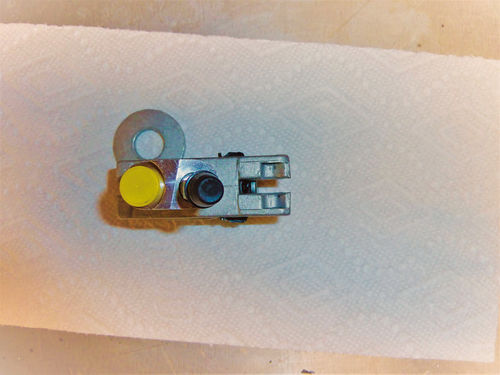
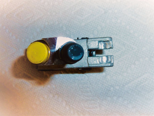
The pivots for this lever are supposed to be recessed in the body of the brake cylinder, allowing it to sit squarely on the backing plate (Photo 7: Rear brake cylinder-before). However, the pivot recess points in my new rear brake cylinders were not deep enough to allow this. About 20 minutes of work with a Dremel tool deepening the pivot points for each brake cylinder took care of this (Photo 8: Rear brake cylinder-after). The flat springs were soon installed, completing the mounting of the brake cylinders. (Photo 9: Wheel cylinder and brake adjuster installed). I was able to deduce the cause of this problem, in part, by comparing my new rear brake wheel cylinders to the old ones that had been removed previously. Never throw away the old part until you are sure of the installation of the new one. Sometimes you may even have to re-use it.
A Battle With the Brake Lines
A humbling experience with brake line installation followed as I struggled to install the lines from the rear brake cylinders to the flexible line pickup point on the backing plates. There was an excellent article by John Armstrong on various tube bending tools in the May issue and I actually have most of the tools described. What I do not have is the talent. (I am firmly of the opinion that while I am mired in three-dimensional space, talented line benders are extra-dimensional—think four or five dimensions.)
Anyway, although I started with prebent lines from Classic Tube, there is always tweaking that must take place. The lines on each side took me almost three hours to adjust to my satisfaction and, in the interim, I discovered that the lines could not be properly fitted with the brake adjusters installed, thereby necessitating removal of the adjusters and re-installation once the lines were fitted (Photo 10: Installed brake line and wheel cylinder).

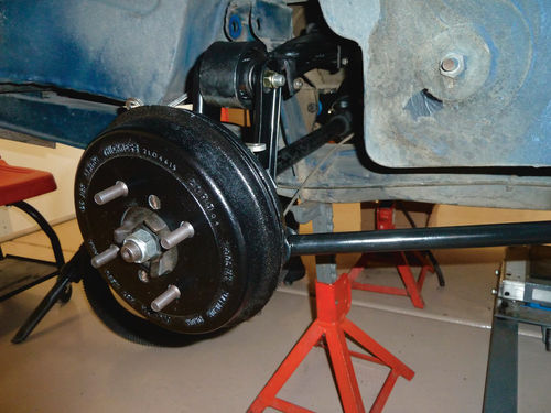
The mounting of new brakes shoes with their associated springs and hold pins was accomplished with only one minor injury, but one of the brake cylinder dust covers was torn in the process. Fortunately, I was able to replace the damaged cover with a dust cover from a rebuild kit without having to remove the brake cylinder (Photo 11: Brake shoes installed). Once the brake shoes were in place, the brake drums, which had been freshened with a coat of Rust-Oleum semi-gloss black paint, were installed and secured with two set screws each (Photo 12: Brake drums installed).
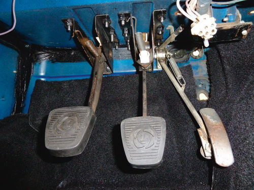
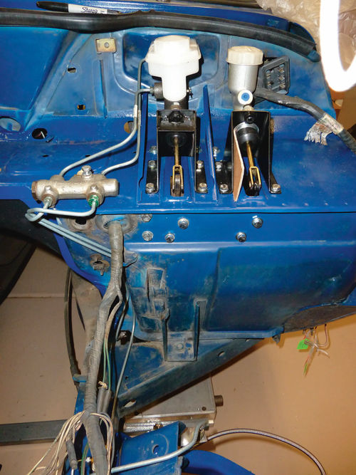
Proceeding with the brake theme, the Spitfire’s pedal assembly was given new pedal pads and bolted into the foot well (Photo 13: Installed pedal assembly). The brackets for the brake and clutch master cylinders, which had earlier been sandblasted to remove the inevitable rust associated with brake fluid and then repainted with Rust-Oleum semigloss black, were mounted on the firewall. A new master brake cylinder from The Roadster Factory was installed and I laid in the brake lines between the brake master cylinder and Pressure Differential Warning Actuator (PDWA) and then from the PDWA to the rear brake line and the front brake calipers (Photo 14: Brake master cylinder). These longer brake line runs proved much easier for me to work as they were already a good fit and required only minor adjustments. (It was necessary to remove the steering column to route the line to the right front brake, but this removal was in the plan regardless as the steering column firewall seal required replacement.) This completed the installation of the Spitfire’s brake lines. Whew!!
Time for a Fuel tank Project
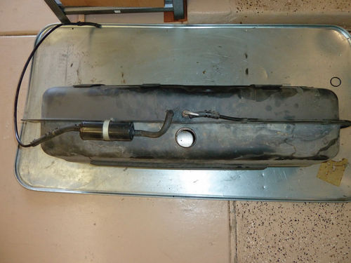
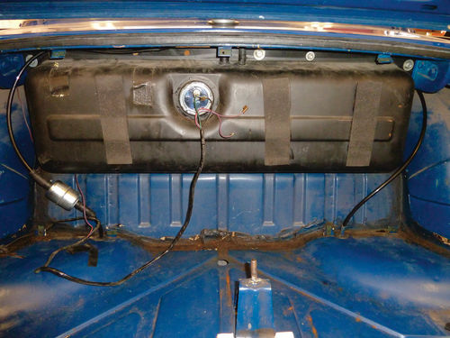
As always, there was time spent awaiting delivery of the parts necessary to move ahead and I used the opportunity to remove and inspect the fuel tank. The Spitfire fuel tank is extremely easy to take out as it is accessible from both the passenger compartment and the trunk. The tank is held in place by five bolts that secure it to the body and, once the rubber fuel filler hose and fuel lines are disconnected and the evaporative loss canister removed, it can be lifted out by one person, assuming that the tank has been drained first (Photo 15: Fuel tank).
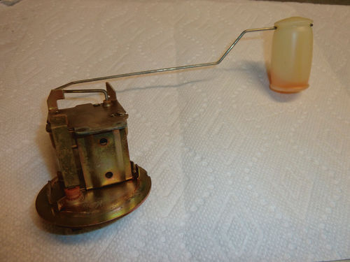
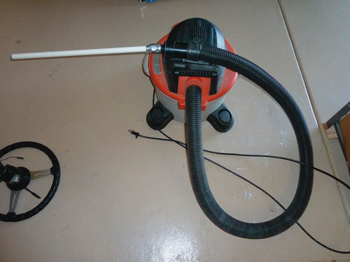
With the fuel tank on my bench I removed the fuel sender unit to ease inspection of the interior. The sender unit appeared to be in good condition although the float had fuel visible in it, evidence of a leak (Photo 16: Old fuel tank sender unit). The tank contained a small amount of stale gasoline, but examination with a mirror and a small flashlight revealed almost no rust and only a few loose particles, probably sand, that were removed using a shop vac modified with a short length of PVC pipe (Photo 17: Shop vac).
The fuel pickup tube was removed, cleaned and reinstalled, and other minor maintenance items were performed including replacement of the fuel filler hose, fuel tank cap grommet, rubber fuel lines and the fuel filter. A new fuel sender unit sourced from Rimmer Brothers (rimmersbros.co.uk) was installed and the tank reunited with the Spitfire (Photo 18: Fuel tank reinstalled).
Help With the Engine Rebuild
Finally, there has been a significant change as to how the Spitfire’s engine rebuild will be accomplished. The original plan was to do the work myself, but as time became a greater factor and I read more on the labor involved, I made the decision to send the engine to be rebuilt professionally. After considering several local engine rebuilders I instead chose TS Imported Automotive of Pandora, Ohio, to do the work (tsimportedautomotive.com).
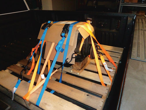
There were several reasons for making this particular choice, but chief among them was that I have met the owner, Ted Schumacher, several times and know him to be conscientious and extremely knowledgeable of Spitfires. On Ted’s advice I arranged for shipping the engine through freightquote.com which provided fine service at a very reasonablecost. The Spitfire’s engine was strapped to a pallet, loaded into the back of my truck and delivered to the local shippers for its journey to Ohio (Photo 19: Engine ready for shipment). By the time you read this, the Spitfire’s engine should be back home in my garage.
Coming Up Next…
There is still much to do with my daughter’s Spitfire, and I am sure that what remains will take longer than anticipated, but I am beginning to catch glimpses of the end.
The list of tasks that I hope to cover in the next installment include charging and bleeding the brakes, reinstalling the steering column, installing the under-car portion of the fuel line and making the engine ready to be mated to the Ford 5-speed transmission which is replacing the original Triumph 4-speed unit. There’s also the decision on whether to retain the existing wiring harness or purchase a new one, a decision that will have to be made soon.


