
Everything I Know About “Bump Steer”
Component Inconsistencies Can Lead to Handling Headaches. So Follow This Advice for a Safer Ride.
HI, FELLOW AUTO Restorer readers. There have been two really good mentions in Auto Restorer from the Mechanic On Duty columnist regarding the phenomenon usually called “bump steer.” With that excellent background, I’d like to pass on to you some practical, firsthand experience as well as some of the details I learned as a suspension engineer during my working career (see note below).
First, since they are very good references, here’s a thumbnail of what’s already been in our favorite magazine, Auto Restorer:
In the June 2012 issue, the Mechanic On Duty advised Ron Lubovich (under the title “My power steering is too powerful”), about what affects steering effort. That included good advice as to proper location and alignment of the steering components to each other in the car (same applies to trucks, of course) as well as caster angle measured from “absolute vertical.” There was no specific mention of “bump steer” but it is totally related and I’m sure that’s among the issues the MOD had in mind.
Then in the August 2012 issue MOD addressed “bump steer” directly in a response to J. D. Jung titled, “Be certain all parts are compatible.” The column used the term “peril” to describe possible results from mixing components; that term is not only accurate but it also describes the urgency needed to point out that the risks from bump steer are high and potentially dangerous. So from that starting point, here are the tidbits I’d like to offer:
First, people have been mixing and matching components since there were cars on the road. Lots of times nothing bad came of it and all seemed well. That could have come from careful planning but it also could have been dumb luck giving that result. (Remember the “Little Deuce Coupe” got “…pushed outta shape and it’s hard to steer…”? Hmmmm, was that just torque steer/wheel-spin or bump steer too?) I’m here to suggest that we leave nothing to chance that could affect the safety of our rides and our passengers.
Second, the term “bump steer” is a good, understandable term for the condition where the wheels literally steer, that is change direction from the driver’s intent, as a result of the wheels moving up and down in response to a bump. And each wheel can react differently if the components aren’t in proper position. Technically, this action is often called “toe steer” as in “change in ‘toe’ alignment” as a result of a bump. At this point you might think these changes in toe are minor and they usually are, in fact, small numbers; often in the range of 1 ⁄2 to 1 or so degrees. But here’s a little test for you to think about so as to get a mental picture: imagine you are driving your well-maintained, very reliable “grocery getter” production car down a straight road free of traffic and you are going (legally, please) at least 60 mph. Give the tires just a small amount of “steer” input; let’s say that’s one degree of tire steering rotation. Since the angular ratio of most OEM steering systems from the driver’s wheel to the tire is 28:1 (or thereabouts) you would have to turn the steering wheel abruptly a full 28 degrees! I hope you’d agree that’s quite extreme! You’ll be across the road in less than a heartbeat! And that one-degree change in the tire’s direction is the result of just less than one-eighth inch (approx, see calc. below) of motion at the tie-rod!
(Calc.: tangent of 1 degree times radius of tire divided by ratio of steering knuckle arm to tire radius: tan 1 deg x 13.5" x ½ = .01746 x 6.75 = .118 inch)
Transplant a Complete System
The way to prevent unwanted bump steer starts just as the MOD wisely advised: “...it’s especially important to be mindful of the need to maintain compatibility among parts.” And I’m sure he meant more than just keeping that beautiful Chrysler 100% Chrysler or whatever your brand of choice may be. When it comes to suspension and steering systems, model years and body styles are often critically important as well.
One good way to avoid a compatibility crisis is to use a completely transplanted system. I know that Mustang II as well as Chrysler Corp. F-Body and M-body (Aspen, Volare, Diplomat, and some New Yorker) front suspensions are popular to “drop in” to a vintage chassis. There are also several great complete suspension systems offered by some suppliers that are totally new components. From what I’ve seen of these they appear to be extremely well-engineered with important and excellent installation instructions. These are all great choices. The only critical factor is to properly locate the new system so that it is square (viewed from the top or bottom), level side-to-side (viewed from the front or rear), and definitely level front-to-rear as viewed from either side or as defined by the supplier’s directions. Or, in the case of recycled parts transplants, according to the vehicle they came out of (Mustang II, Aspen, Volare, etc.).
The Four Bar Link
OK, that’s the general picture. Here’s what’s really going on.
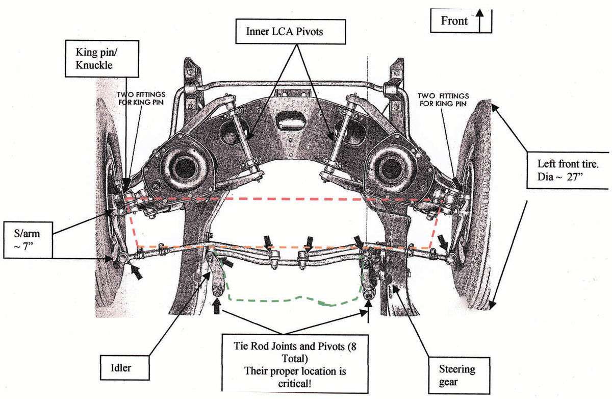
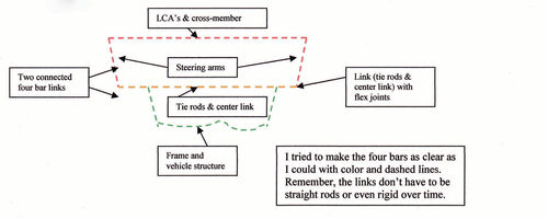
Most of the connections in the front suspension and steering of an automotive product are made up of “four-bar links.” These are great for giving accurate, strong, repeatable, durable motion during the life of the vehicle. And the front suspension and steering are full of these linkages. The LCA (lower control arm) to knuckle to UCA (upper control arm) to frame is one “four bar” on each side. The tie-rods (both or all) to knuckle arms to control arms (yup, both lower and upper act as one link) to frame are another, complicated example. So is the pitman-arm to tie-rod(s) to idler-arm to frame another “four-bar.” None of these are mysteries; there are just lots of individual parts and each has to be looked at in all three perspectives (front/rear, side to-side, and top/bottom) which makes it complicated to keep track of everything.
But they have their constraints and requirements. Here’s another example: if the right side idler arm connection to the tie rod is low, when the car hits a bump with that right side tire that right wheel will “toe” outward (the knuckle’s steering arm is to the rear of the knuckle) as it goes upward (you can visualize that as moving in a “right turn” direction) more than it should. The driver will probably feel the car try to turn right a little or a lot; sometimes it’s called “lead right.” And since we know that small movements can make a pretty big difference (mental experiment, above), then small amounts of mis-location can add up to significant troubles.
Experience as a Guide
The good news is, all of us who dabble in car building, restoring and shadetree mechanic work need to do just one thing — keep track of all the parts and how they are mounted. We just have to do it for several parts and sometimes more than once to be sure the job is done right.
Since I’ve stumbled through this process a couple of times, here’s a few general how-to guidelines that I learned the hard way. If you know any steps to perfect this, don’t hold back, go for it:
• Small things mean a lot! Don’t settle for 1 ⁄8-inch being OK, go for getting everything to within 1 ⁄32-inch; that’s usually as close as you can measure with a steel tape (be sure to use the same steel tape for all measurements to avoid unaccounted for errors). (Disclaimer: Sure, somebody will say that they had something within 1 ⁄8-inch and it was just fine. Maybe they did. Then again, I’ve seen race cars that fell off the trailer, bending the suspension and they went on to run their best ever — those guys were the recipients of some great “dumb luck.”)
• Now, if I made the point that small things mean a lot, here’s the general rules in very, very brief form:
Keep each pivot point as close to exactly the same as its mate. That is, tie rod inners each the same distance from center, same height from floor (horizontal plane of the car) and same distance fore/aft to the ball joints. Tie rod idler pivots, same rules. Idler frame pivot same as output (sector) shaft of the steering gear. Ball joints, same rules; distance to centerline, height, fore/ aft locations all the same for right and left side. Control arms, same rules, plus the inner pivot arms/bars must be at the same angles to centerline and vertical and horizontal planes. And all those dimensions are checked at normal “ride height” of the car/wheels; when the wheel travels in either bump (compression) or rebound (extension) the angled links will divert from the “zeroed in” position. That’s OK as long as they are set correctly to begin with. Your result will be wheels that stay pointed in the direction you want them to go and they won’t “steer” (toe change) away from their ideal position.
• Start square and true with the frame and cross-members. Find a good flat spot in your shop floor (most of us don’t have access to a framing plate). Then with the car as completely built as possible (power train installed, body complete, interior installed, etc. so that the frame is loaded as in normal operation) check side-to-side heights and shim (or bend?) to get it level. Then square it up so the frame rails are the same fore to aft. And also front to rear correct to specs and identical side-to-side.
• Check and re-check the suspension cross-member (K-frame) for its accuracy. Again, check front-to-rear, side-to-side, and vertical. Be really critical of the control arm, steering gear/rack, and idler attachment points. The steering gear/rack is SUPER critical for location as well as structural integrity. And don’t forget, each part is likely a part of a “four-bar link” and many of these are mirrored on each side of the vehicle so they must be identical to their complement on the other side.
• I’d advise re-checking the parts as they are assembled to the car. That is, check the cross-member once it is on the frame. Then check the location of the steering gear/rack again very carefully; also an idler arm mount and idler pivot must be level with the steering gear (and idler pivot must perfectly match the end pivot of the pitman arm) and a steering rack MUST be level to the frame, cross-member, ground, and centered in the frame (between LCA pivots). The same goes for the control arms; the lower is the most critical here; be sure the inner pivots are level side-to-side and tilted at the identical angles between the left and right. In this case, it can be better to have the LCA inner pivots slightly “wrong” in their angles to the car as long as the right and left side pivots are exactly the same to each other. In bump steer it’s small differences in the various components within the multiple “four-bar links” that cause some of the biggest problems.
• As you add the control arms and knuckles be sure to start setting the alignment as the parts are added. Camber and caster can be pre-set using an inclinometer (or bubble alignment gauge). Toe can be pre-set using the old string trick between the front and rear tires/wheels. Here it might be good to check the fronts together using the steel tape if you can get to the front and back of the tire at (or very near) the height of the wheel center.
• By this time you’re probably ready to button this job up and cruise down the road. I would suggest another step if you want to be sure that you won’t have to bring the car back in and risk doing it all over again and/or risk damaging some of that beautiful chassis black paint on your freshly restored beauty. Also, this is the best time to look for and find anything that is different side-to-side or front-to back or top-to-bottom in the system; and, after all, that’s what is critical in bump steer. So don’t put in the springs just yet (assuming it’s an independent, coil spring system, IFS). Snug up the fasteners to hold the components in place and “jack up” the tires until the spindles are near the normal “ride height” for your vehicle. Now, with all the components (frames, cross-members, brackets, arms, links, sway bars, steering in (what should be) the correct place, you can double-check the critical stuff (steering, control arms, and idlers) as well as whatever you can get to. This way you can be sure there is no binding condition or something you missed that will affect the finished job. And a check of alignment will be good to do at this time.
• Now it’s time to put in the springs (tighten all the bushing joints with the car at “ride height” to avoid bind-up in any rubber bushings) and head to the alignment shop for what should be a minor adjustment of a well-built car.
Some Lessons From the Track
As an added thought from past experience, we combined these last two steps for our “circle track” race truck a few years ago. Since we were competing in the 1 ⁄4- to 1 ⁄2-mile tracks in the region we needed all the good handling we could get. So after a lot of frustration and trackside “adjusting” we built and set everything as “right” as we could get it and then assembled the truck without the springs (and less sway bar in our case), using a “bubble gauge” for camber and caster and steel tapes for toe. We moved the front wheels up and down individually and together an inch or so at a time. By keeping track of the changes in toe (mostly) as well as caster and camber, we created “alignment patterns.” Toe patterns should be pretty much straight lines, close to vertical for each wheel. In doing this we found some small but crucial errors in the suspension. At this point it was fairly easy to spot them and correct them right then and there. Had we rushed the job and skipped this step we would have been guessing and “adjusting” everything in total ignorance at the track, AGAIN! Let me tell you that whoever said, “second place sucks” never kissed the wall coming out of turn #4 because of an ill-handling vehicle! That’s what really sucks.
So in parting, the high points are: little things mean a lot, keep the left & right paired parts as close to identical as you can, and vertical dimensions are most important with lateral and fore/aft dimensions close behind.
That’s my story. Maybe not too scientific but I hope you will find it adds a bit of insight to your project and, hopefully, a little help.
Keep those cool cars rollin’. …And LOVE that Auto Restorer magazine!
Note: There are some great references out there suitable to both the performance-minded as well as restorers and hot rodders. I’m familiar with the offerings from Mopar Performance including: “Chassis — Speed Secrets & Modifications For Chrysler RWD Racing Cars” as well as “Oval Track Modifications.” Both are available from your local Chrysler, Jeep, Dodge, Ram, SRT dealer and probably somewhere on the Internet as well.
Also, there are computer programs to assist with a multitude of chassis projects. Since digital technology changes so fast I’ll let you search the Internet for the latest and greatest to fit your project and your computer device.


